2 internal battery breaker, Access to the terminals for the cable connections – GE Industrial Solutions LP33 Series 80 & 100 Installation Guide User Manual
Page 28
Modifications reserved
Page 28/47
OPM_LPS_3UI_80K_M10_1US_V010.doc
Installation Guide LP33 Series 80 & 100 UL S1
Access to the terminals for the cable connections
LPS33U_0
80-100_Co
nnection_
01US
A
Bottom
entry cables
Q2
Q1
F11
F12
F13
B
C
D
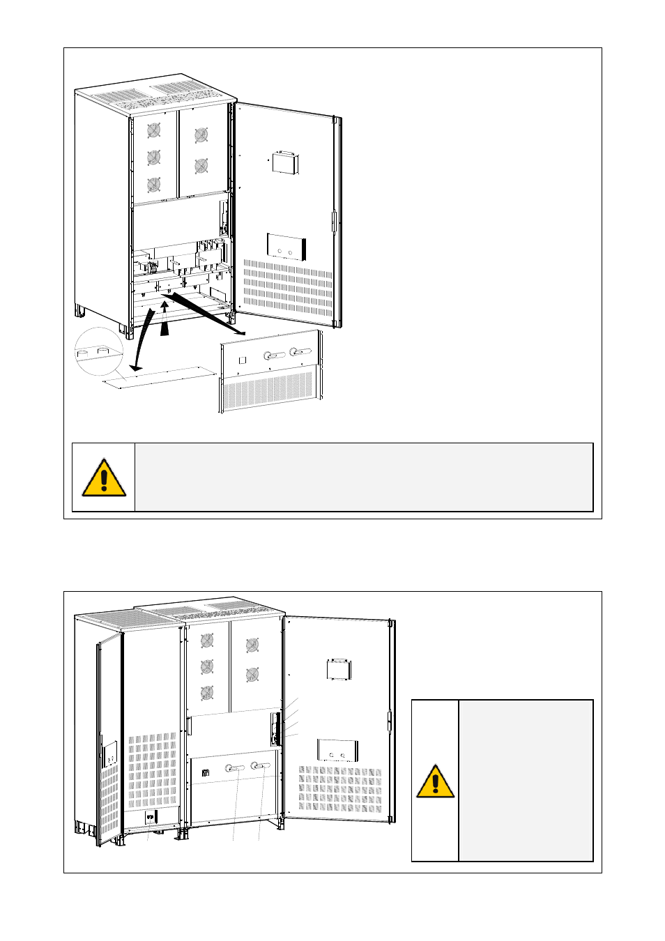
Fig. 3.8.1-1 Access to the input / output connections
To access input, output and battery
connections proceed as follows:
• Open the front door “A” of the cabinet.
• Remove the protection panel “B”.
• Remove the plate “C” for bottom cable
entry.
NOTE !
Drill in the plate “C” appropriate holes for cable conduits (max. 4 x 2 1/2”).
Please remove the plate “C” before drilling any holes.
See Fig 3.8.1-1 - details “C & D”.
3.8.2 Internal Battery Breaker
The option Battery cabinet is
equipped with Breaker FTM3.
In case of replacement the same
type and the same rating must be
used.
WARNING !
Wrong polarity
connection can cause
hazard to UPS and
personal.
The replacement of
Battery Breaker FTM3
must be performed by
QUALIFIED SERVICE
PERSONAL only.
LPS33U_080-100_UPS+Battery cabinet 0650_02
Q2
I ON
0 O
FF
F11-12-13
Q1
I ON
0 O
FF
SNMP
CI
RS232
RC
Q2
Q1
FTM3
Fig. 3.8.2-1 Battery Breaker