3 battery over current protection and wire sizing, Utility input, Load – GE Industrial Solutions LP33 Series 80 & 100 Installation Guide User Manual
Page 23
Modifications reserved
Page 23/47
OPM_LPS_3UI_80K_M10_1US_V010.doc
Installation Guide LP33 Series 80 & 100 UL S1
LPS33U_080-100_RPA system_GE_01US
Digital Energy
g
UPS System
F1
F2
F3
F4
UTILITY INPUT
LP33 Series 80 & 100
1
2
3
4
LOAD
RPA
Board
RPA
Board
RPA
Board
RPA
Board
Digital Energy
g
UPS System
Digital Energy
g
UPS System
Digital Energy
g
UPS System
LP33 Series 80 & 100
LP33 Series 80 & 100
LP33 Series 80 & 100
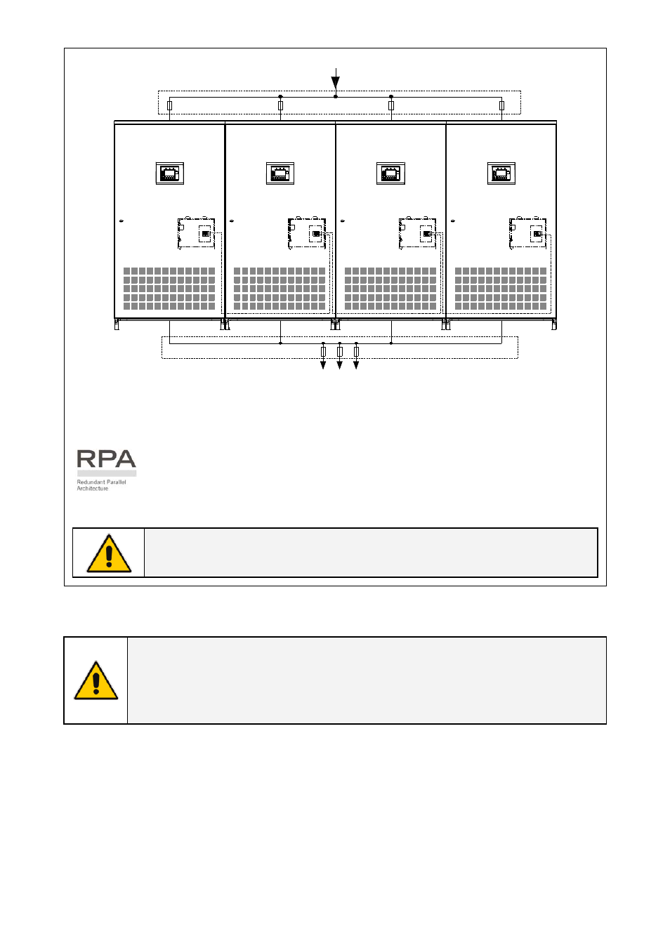
Fig. 3.7.2-1 RPA Parallel System
In order to ensure a correct load sharing between the parallel units, when the Load is
supplied by Utility, it is recommended to keep the cable size and length from the
input distribution board to the output busbar the same for each parallel unit.
Utility Bypass Input Voltage must be the same for all units, thus avoiding phase shift
or phase rotation problems.
To avoid mutual induction effect, the input cables bust be run in separate conduit
from the output cables.
NOTE !
No transformers, fuses or automatic circuit breakers should be inserted between
the unit’s output and the load common busbars.
The delivery and installation of fuses and input / output connections of the UPS are at the
customer’s expense, unless agreed otherwise.
NOTE !
It is recommended to provide an additional length of the input/output cables so that
the UPS can be moved for maintenance purpose.
It is recommended to use flexible input/output conductors with suitable length to
admit a sufficient displacement.
3.7.3 Battery over current protection and wire sizing
•
Please read the safety precautions at the front of this guide carefully, and thoroughly review the
battery manufacturer’s installation and maintenance manual before connecting the batteries to
the UPS.
•
Choose an appropriate DC fuse or circuit breaker using the current data in the chart below.
•
Minimum battery cable requirement is based on the current data below.