Front – GE Industrial Solutions LP33 Series 80 & 100 Installation Guide User Manual
Page 17
Modifications reserved
Page 17/47
OPM_LPS_3UI_80K_M10_1US_V010.doc
Installation Guide LP33 Series 80 & 100 UL S1
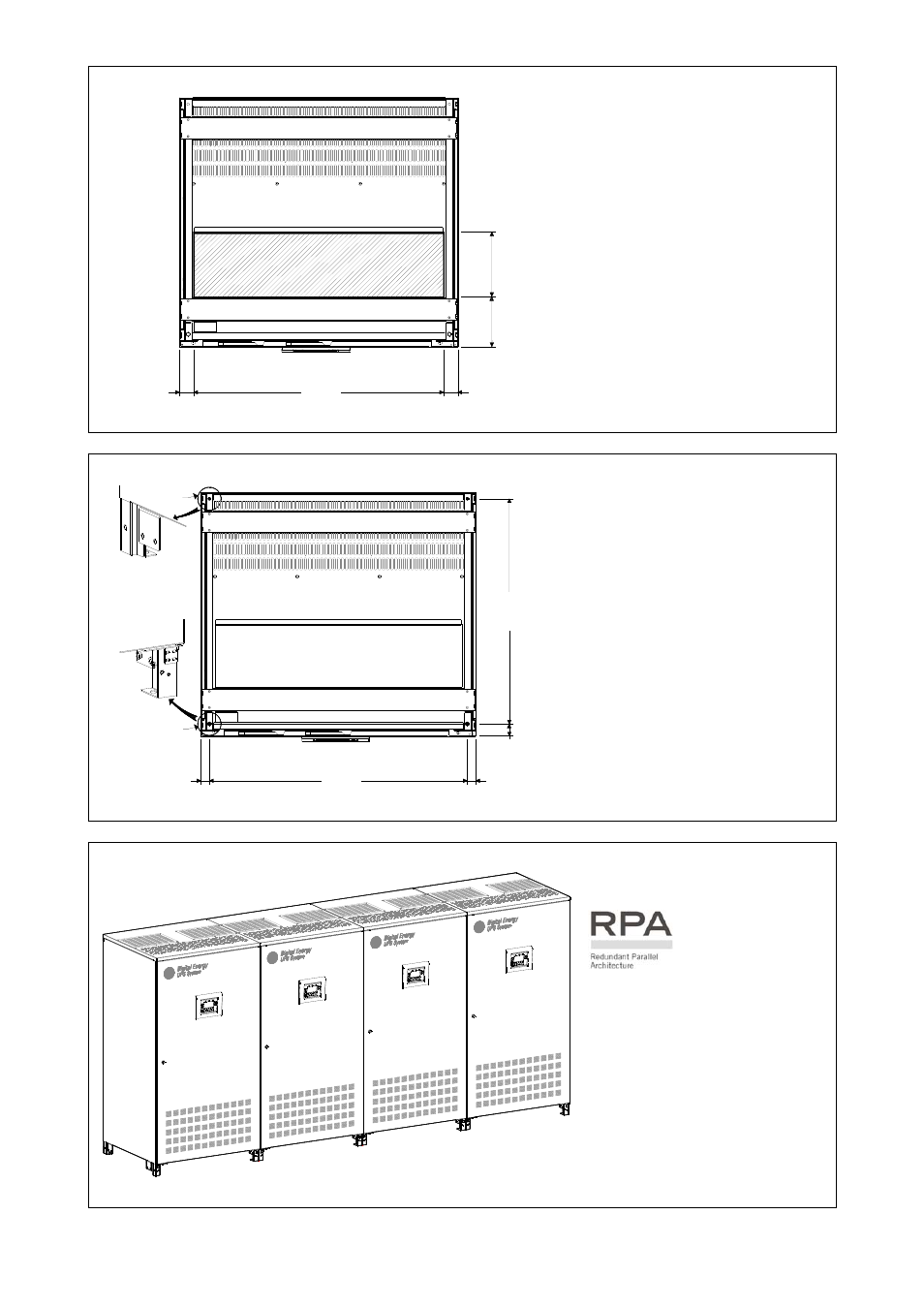
Opening for input and output cable connections LP33 Series 80 & 100
Front
230mm
9.0
6"
18
2mm
7.17
"
900mm
50mm
50mm
35.44"
1.97"
1.97"
LP
S33U
_080
-100
_UPS
v
ie
w
bo
tt
om
_0
1
Fig. 3.4-2 Opening on the bottom of the cabinet for input and output cables
LP33 Series 80 & 100 opening is
provided on the bottom of the UPS
for the connection of input and
output cables.
Pay attention to the position of this
opening, when choosing the
placement of the UPS.
Fixing of the UPS cabinet LP33 Series 80 & 100 on the floor
Ø 12mm
Ø 0.47"
LPS33U_080-100_UPS fixing_01
Front
830m
m
32.
68"
46mm
1.
78"
940mm
31.5mm
31.5mm
37.00"
1.24"
1.24"
Ø 12mm
Ø 0.47"
Fig. 3.4-3 UPS cabinet floor fixing points
The UPS cabinet is free standing and
normally does not require to be
bolted to the floor.
The UPS cabinet can be fixed
however to the floor by bolting it
with the supporting blocks to the
floor.
Positioning of the LP33 Series 80 & 100 Parallel System
LPS33U_0
80-100_R
PA disposi
tion_GE_0
1
1
4
3
2
Fig. 3.4-4 RPA system disposition
The UPS cabinet is free standing
and normally does not require
to be bolted to the floor.
The UPS cabinet can be fixed
however to the floor by bolting
it with the supporting blocks to
the floor.