GE Industrial Solutions GPS4827 User Manual
Page 80
Galaxy Power System GPS4827
78
1. The plant voltage must be above the level set for the High
Voltage alarm at the VOLTAGE ALARMS menu screen:
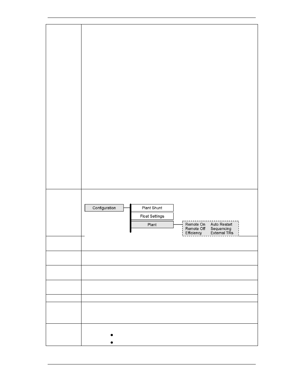
MENUCONFIGUREFLOAT SETTINGSVOLTAGE ALARMS
2. The rectifier must be delivering a current of at least 10% of its
capacity.
3. The rectifier’s current output must be unbalanced by more than
10% from the average output currents of the other rectifiers.
Because item 3 is difficult to achieve in a simulation test of properly
functioning serial rectifiers, (even with load share disabled), rectifiers
are tested one at a time, rather than as a group. Slightly different test
procedures are used for special applications in batteryless plants. Serial
rectifiers have their own internal restart circuits which will function 3
times before the rectifier locks itself out and initiates a High Output
Rectifier Fail Alarm to the controller. If there is a sufficient interval
between restart and a subsequent shutdown the rectifier resets its
restart counter. The controller initiates a restart signal a few seconds
after the
first RFA (HO) alarm is received. After the second RFA (HO) is received,
the controller waits 5 minutes before sending one additional restart
signal.
1.
Verify the Auto Restart is enabled from the front panel menus:
2.
Turn off all rectifiers except the rectifier under test by operating their
power switches to STBY.
3.
Adjust the dummy load to provide 10 to 30% of the rectifier’s output
capacity.
4.
Using the Voltage Alarms Menu Screens, note High Voltage Alarm
threshold value. _________
5.
Using the Float Settings Menu Screens, select Set Point and note the
value. ________
NOTE:
The next step WILL RAISE the system voltage.
6.
Use the Arrows, and UP/DOWN keys to change the system float voltage
setpoint to 0.1V above the High Voltage Alarm Threshold.. Press ENTER
to save.
7.
Controller Observations:
The plant voltage increases
Power Major alarm (PMJ) is generated