Thermal probes – GE Industrial Solutions GPS4827 User Manual
Page 44
Galaxy Power System GPS4827
42
the address.
7.
Carefully attach the control unit to the connection unit using the ribbon
connector.
NOTE:
This connector/cable is not keyed, so be careful to line up the pins
properly.
8.
After approximately 1 minute, the green LED on the front of the module
will blink once approximately every 5 seconds. Detailed troubleshooting
information may be found in the User’s Guide for Millennium II Controller
Advanced Features manual.
Thermal Probes
Without thermal probes, many of the controller’s battery management features will
not function, or produce erroneous results. Some features requiring thermal inputs
are:
Slope Thermal Compensation
Reserve Time Prediction
High Temperature Alarm
Ambient High and Low Temperature Alarms
High Temperature Disconnect
Step
Action
NOTE:
The controller supports a number of thermal probe inputs. The type of
probe used determines where it is connected on the controller. Detailed
thermal probe and battery management information may be found in the
User’s Guide for Millennium II Controller Advanced Features manual.
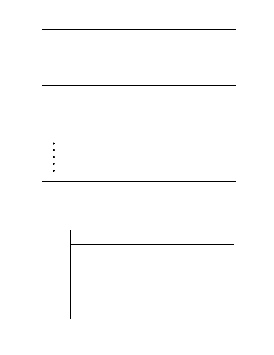
1.
The following table shows the type of probe and connector location on the
Millennium:
Type of Probe
Comcode
Controller Connection
Location
10/30K
P3
210E Thermal Probe
Mux
P3
1 Wire Temperature
Monitoring Devices
P7
Terminal Block
Interface for 3
additional 10k probes
or 210E connection
TB2
Pin
Description
1
Probe 2
2
Probe 2 RTN
3
Probe 3