GE Industrial Solutions GPS4827 User Manual
Page 51
Galaxy Power System GPS4827
49
Rectifier Sequence Option
The controller is capable of sequencing rectifiers on line after detecting a AC is being
provided by emergency generator. Internal Rectifier Sequencing requires external
wiring to ETR/ETRR on BSL pin numbers 75/76, and optionally RO/ROR on BSL pin
numbers 77/78, in order to function.
The controller can also accept ground signals onto TR1 to TR4 on BSL 73/79/ 85/80
from an external device to control the sequencing of plant rectifiers in groups as
follows:
Table 9-D: TR leads and Associated Rectifiers
TR
Signal
Rectifiers Affected
TR1
G01, G02, G09, G10, G17, G18, G25, G26, G33, G34, G41, G42, G49, G50,
G57, G58
TR2
G03, G04, G11, G12, G19, G20, G27, G28, G35, G36, G43, G44, G51, G52,
G59, G60
TR3
G05, G06, G13, G14, G21, G22, G29, G30, G37, G38, G45, G46, G53, G54,
G61, G62
TR4
G07, G08, G15, G16, G23, G24, G31, G32, G39, G40, G47, G48, G55, G56,
G63, G64
Additional information on the Rectifier Sequence Options can be found in the User’s
Guide for Millennium II Controller Advanced Features manual.
Battery Temperature Option
Slope Thermal Compensation and Battery Reserve Time Prediction features of the
controller, require that battery temperature be monitored. If either of these features
is to be configured in Galaxy software, a battery temperature input must be
connected to P3 temperature probe connector on the Controller board.
Three optional cables are used to connect to various battery arrangements:
Cable Assembly
Connects to:
848152997
KS20472 round cell thermistor
848152989
ring or paddle type thermistors
848153003
210E Thermal Probe Multiplexer
Refer to User’s Guide for Millennium II Controller Advanced Features manual for
additional information on these features.
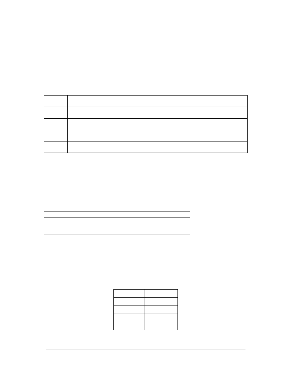
Alarm Battery Supply Signals
Table 9-E: ABS Pin Numbers
Signal Name
Pin No.
ABS
93
ABS
94
DG
95
DG
96