Package information, Chip information, Pin configuration – Rainbow Electronics MAX3942 User Manual
Page 10
MAX3942
10Gbps Modulator Driver
Maxim cannot assume responsibility for use of any circuitry other than circuitry entirely embodied in a Maxim product. No circuit patent licenses are
implied. Maxim reserves the right to change the circuitry and specifications without notice at any time.
10 ____________________Maxim Integrated Products, 120 San Gabriel Drive, Sunnyvale, CA 94086 408-737-7600
© 2003 Maxim Integrated Products
Printed USA
is a registered trademark of Maxim Integrated Products.
Package Information
For the latest package outline information, go to
www.maxim-ic.com/packages
.
Exposed-Pad Package
The exposed pad on the 24-pin QFN provides a very
low thermal resistance path for heat removal from the
IC. The pad is also electrical ground on the MAX3942
and must be soldered to the circuit board ground for
proper thermal and electrical performance. Refer to
Maxim Application Note HFAN-08.1: Thermal
Considerations for QFN and Other Exposed-Pad
Packages for additional information.
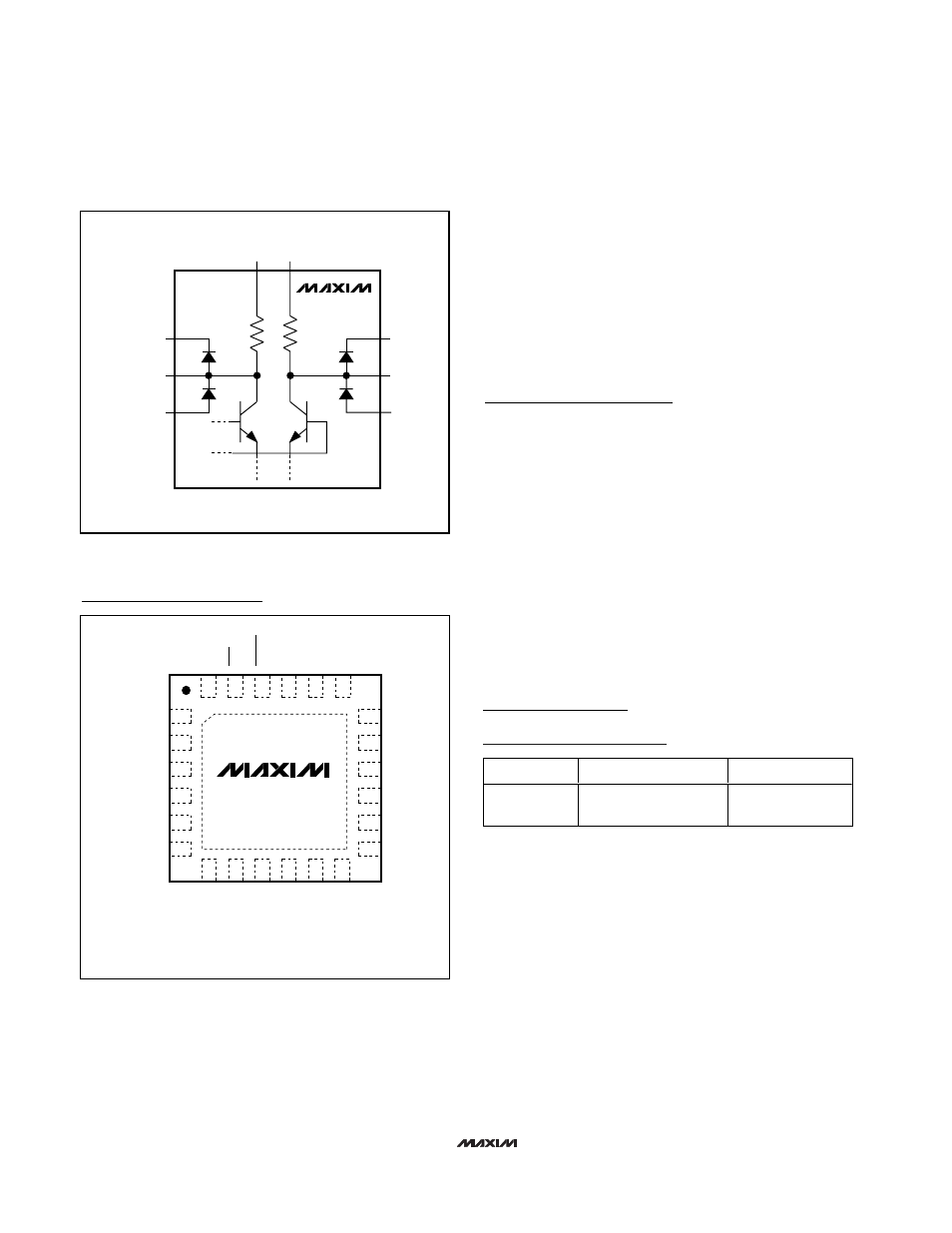
Figure 6. Simplified Output Circuit
MAX3942
50
Ω
50
Ω
OUT+
GND
V
EE
OUT-
GND
V
EE
GND
GND
Chip Information
TRANSISTOR COUNT: 1918
PROCESS: SiGe Bipolar
24
23
22
21
20
19
7
8
9
10
11
12
13
14
15
16
17
18
6
5
4
3
2
1
MAX3942
24 THIN QFN (4mm x 4mm)
TOP VIEW
DATA+
DATA-
GND
GND
CLK+
CLK-
EXPOSED PAD CONNECTED TO GROUND
V
EE
RTEN
MODEN
V
EE
PLRT
V
EE
V
EE
GND
OUT+
OUT-
GND
V
EE
V
EE
V
EE
MODSET
PWC-
PWC+
V
EE.
Pin Configuration
PART
PACKAGE TYPE
PACKAGE CODE
MAX3942ETG
24 Thin QFN
(4mm
✕
4mm
✕
0.8mm)
T2444-1