Rainbow Electronics MAX3942 User Manual
General description, Features, Applications
General Description
The MAX3942 is designed to drive high-speed optical
modulators at data rates up to 10.7Gbps. It functions as
a modulation circuit, with an integrated control op amp
externally programmed by a DC voltage.
A high-bandwidth, fully differential signal path is internally
implemented to minimize jitter accumulation. When a
clock signal is available, the integrated data-retiming
function can be selected to reject input-signal jitter.
The MAX3942 receives differential CML signals (ground-
referenced) with on-chip line terminations of 50
Ω. Each
of the differential outputs has an on-chip 50
Ω resistor for
back termination. The driver is able to deliver a modula-
tion current of 40mA
P-P
to 120mA
P-P
, with an edge
speed of 23ps (typical 20% to 80%). This modulation cur-
rent reflects a modulation voltage of 1.0V
P-P
to 3.0V
P-P
single ended or 2.0V
P-P
to 6.0V
P-P
differential.
The MAX3942 also includes an adjustable pulse-width
control circuit to precompensate for asymmetrical mod-
ulator characteristics. It is available in a compact 4mm
✕
4mm, 24-pin thin QFN package and operates over
the -40°C to +85°C temperature range.
Features
♦ 23ps Edge Speed
♦ Single-Ended Modulation Voltage Up to 3V
P-P
♦ Differential Modulation Voltage Up to 6V
P-P
♦ Selectable Data-Retiming Latch
♦ Up to 10.7Gbps Operation
♦ 50Ω On-Chip Input and Output Terminations
♦ Pulse-Width Adjustment
♦ Enable and Polarity Controls
♦ ESD Protection
Applications
Mach Zehnder Modulators
Packaged Direct-Modulated Lasers
SONET OC-192 and SDH STM-64 Transmission
Systems
DWDM Systems
Long/Short-Reach Optical Transmitters
10Gbps Ethernet
MAX3942
10Gbps Modulator Driver
________________________________________________________________ Maxim Integrated Products
1
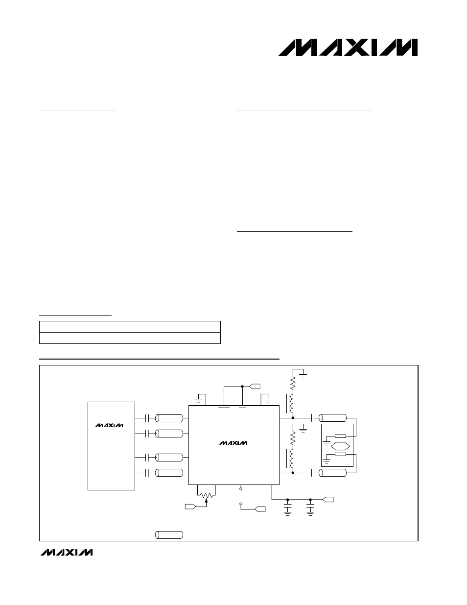
MAX3952
0.01
µF
DATA+
DATA+
PLRT
GND
50
Ω
0.01
µF
DATA-
DATA-
50
Ω
0.01
µF
CLK+
CLK+
OUT+
50
Ω
0.01
µF
CLK-
CLK-
REPRESENTS A CONTROLLED-IMPEDANCE TRANSMISSION LINE.
-5.2V
50
Ω
10Gbps
SERIALIZER
2k
Ω
PWC+
PWC-
V
EE
MODSET
+
V
MODSET
-
1000pF
-5.2V
-5.2V
0.1
µF
-5.2V
MODEN
RTEN
50
Ω
OUT-
50
Ω
MAX3942
L2
L1
50
Ω
50
Ω
0.01
µF
0.01
µF
MACH ZEHNDER
MODULATOR
L1 AND L2 ARE HIGH-FREQUENCY FERRITE BEADS
Typical Application Circuit
19-2934; Rev 0; 7/03
For pricing, delivery, and ordering information, please contact Maxim/Dallas Direct! at
1-888-629-4642, or visit Maxim’s website at www.maxim-ic.com.
Ordering Information
PART
TEMP RANGE
PIN-PACKAGE
MAX3942ETG
-40°C to +85°C
24 Thin QFN (4mm
✕
4mm)
Pin Configuration appears at end of data sheet.