Rainbow Electronics DS2165Q User Manual
Page 8
DS2165/DS2165Q
041295 8/17
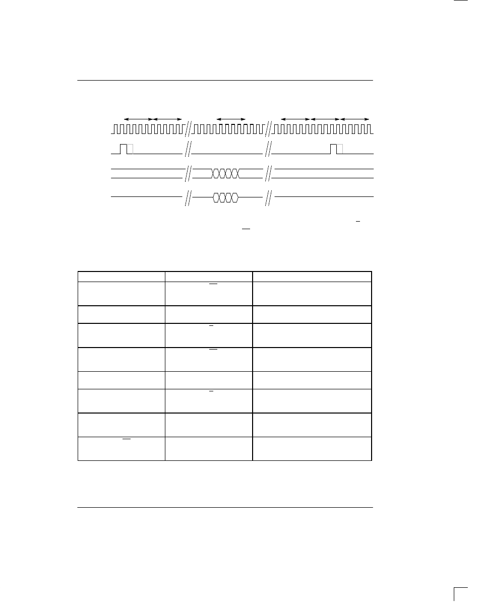
DS2165 A-LAW ADPCM INTERFACE Figure 10
TIME
SLOT 0
TIME
SLOT 1
TIME
SLOT N
TIME
SLOT 62
TIME
SLOT 63
TIME
SLOT 0
CLKX, CLKY
FSX, FSY
XIN, YIN
XOUT, YOUT
MSB
LSB
DON’T CARE
3-STATE
DON’T CARE
3-STATE
MSB
LSB
HARDWARE MODE
The hardware mode is intended for applications that do
not have an external controller available or do not re-
quire the extended features offered by the serial port.
Tying the SPS pin to V
SS
disables the serial port, clears
all internal register bits and maps the IPD, U/A, and
CP/EX bits for both channels to external bits. (See Table
3.) In the hardware mode, both the input and output time
slots default to time slot 0.
HARDWARE MODE Table 3
PIN # / NAME
REG. LOCATION
NAME AND DESCRIPTION
4 / A0
CP/EX
(Channel X)
Channel X Coding Configuration
0 = Expand
1 = Compress
5 / A1
AS0/AS1/AS2
(Channel X & Y)
Algorithm Select (see Table 5)
6 / A2
U/A
(Channel X)
Channel X Data Format
0 = A-law
1 =
µ
-law
7 / A3
CP/EX
(Channel Y)
Channel Y Coding Configuration
0 = Expand
1 = Compress
8 / A4
AS0/AS1/AS2
(Channel X & Y)
Algorithm Select (see Table 5)
9 / A5
U/A
(Channel Y)
Channel Y Data Format
0 = A-law
1 =
µ
-law
18 / SDI
IPD
(Channel Y)
Channel Y Idle Select
0 = Channel active
1 = Channel idle
19 / CS
IPD
(Channel X)
Channel X Idle Select
0 = Channel active
1 = Channel idle
NOTES:
1. SCLK must be tied to V
SS
when the hardware mode is selected.
2. When both channels are idled, power consumption is significantly reduced.
3. The DS2165 will power-up within 800 ms after either channel is returned to active from an idle state.