Rainbow Electronics DS2165Q User Manual
Page 5
DS2165/DS2165Q
041295 5/17
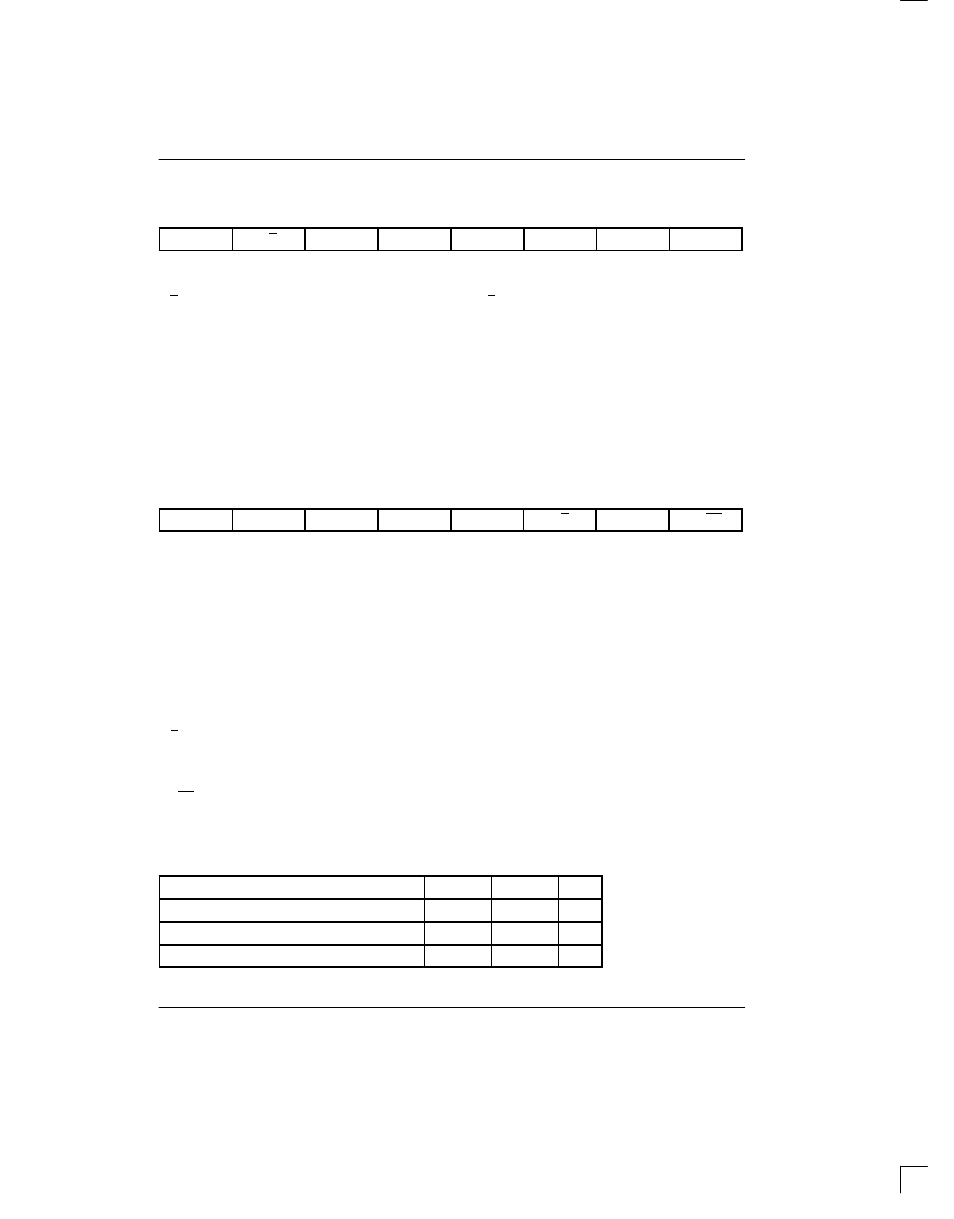
ADDRESS/COMMAND BYTE Figure 3
(MSB)
(LSB)
–
X/Y
A5
A4
A3
A2
A1
A0
SYMBOL
POSITION
NAME AND DESCRIPTION
–
ACB.7
Reserved; must be 0 for proper operation
X/Y
ACB.6
X/Y Channel Select
0 = update channel Y characteristics
1 = update channel X characteristics
A5
ACB.5
MSB of Device Address
A4
ACB.4
A3
ACB.3
A2
ACB.2
A1
ACB.1
A0
ACB.0
LSB of Device Address
CONTROL REGISTER Figure 4
(MSB)
(LSB)
AS0
AS1
IPD
ALRST
BYP
U/A
AS2
CP/EX
SYMBOL
POSITION
NAME AND DESCRIPTION
AS0
CR.7
Algorithm Select 0. See Table 2.
AS1
CR.6
Algorithm Select 1. See Table 2.
IPD
CR.5
Idle and Power Down.
0 = channel enabled
1 = channel disabled (output 3-stated)
ALRST
CR.4
Algorithm Reset.
0 = normal operation
1 = reset algorithm for selected channel
BYP
CR.3
Bypass.
0 = normal operation
1 = bypass selected channel
U/A
CR.2
Data Format.
0 = A-law
1 =
µ
-law
AS2
CR.1
Algorithm Select 2. See Table 2.
CP/EX
CR.0
Channel Coding.
0 = expand (decode) selected channel
1 = compress (encode) selected channel
ALGORITHM SELECT BITS Table 2
ALGORITHM SELECTED
AS2
AS1
AS0
64Kbps to/from 32Kbps
0
0
0
64Kbps to/from 24Kbps
1
1
1
64Kbps to/from 16Kbps
1
0
1