Attiny2313 – Rainbow Electronics ATtiny2313 User Manual
Page 37
37
ATtiny2313
2543A–AVR–08/03
Note:
1. V
BOT
may be below nominal minimum operating voltage for some devices. For
devices where this is the case, the device is tested down to V
CC
= V
BOT
during the
production test. This guarantees that a Brown-Out Reset will occur before V
CC
drops
to a voltage where correct operation of the microcontroller is no longer guaranteed.
The test is performed using BODLEVEL = 110 for ATtiny2313V and
BODLEVEL = 101 for ATtiny2313L.
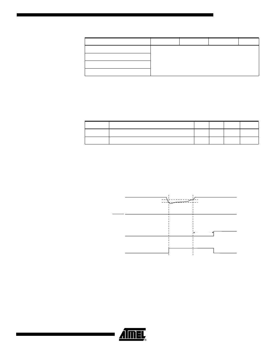
When the BOD is enabled, and V
CC
decreases to a value below the trigger level (V
BOT-
in Figure 18), the Brown-out Reset is immediately activated. When V
CC
increases above
the trigger level (V
BOT+
in Figure 18), the delay counter starts the MCU after the Time-
out period t
TOUT
has expired.
The BOD circuit will only detect a drop in V
CC
if the voltage stays below the trigger level
for longer than t
BOD
given in Table 15.
Figure 18. Brown-out Reset During Operation
011
Reserved
010
001
000
Table 17. Brown-out Characteristics
Symbol
Parameter
Min
Typ
Max
Units
V
HYST
Brown-out Detector Hysteresis
50
mV
t
BOD
Min Pulse Width on Brown-out Reset
2
ns
Table 16. BODLEVEL Fuse Coding
(1)
BODLEVEL 2..0 Fuses
Min V
BOT
Typ V
BOT
Max V
BOT
Units
V
CC
RESET
TIME-OUT
INTERNAL
RESET
V
BOT-
V
BOT+
t
TOUT