Reading the calibration byte, Parallel programming characteristics, Attiny2313 – Rainbow Electronics ATtiny2313 User Manual
Page 171: And t, Also apply to loading operation
171
ATtiny2313
2543A–AVR–08/03
Reading the Calibration Byte
The algorithm for reading the Calibration byte is as follows (refer to “Programming the
Flash” on page 166 for details on Command and Address loading):
1.
A: Load Command “0000 1000”.
2.
B: Load Address Low Byte, 0x00.
3.
Set OE to “0”, and BS1 to “1”. The Calibration byte can now be read at DATA.
4.
Set OE to “1”.
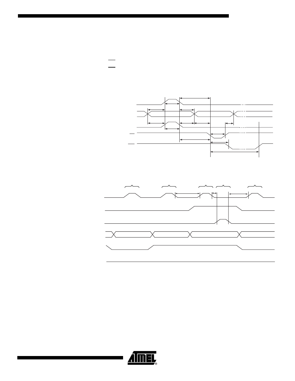
Parallel Programming
Characteristics
Fi gu re 7 4. P ara llel P ro gra m m ing Tim in g, In clu din g s om e G e ne ra l T im ing
Requirements
F ig u re 7 5 . P a ra l le l P ro g ra m m in g Ti m in g , L o a d in g S e q u e n ce w it h Ti m in g
Requirements
(1)
Note:
1. The timing requirements shown in Figure 74 (i.e., t
DVXH
, t
XHXL
, and t
XLDX
) also apply
to loading operation.
Data & Contol
(DATA, XA0/1, BS1, BS2)
XTAL1
t
XHXL
t
WLWH
t
DVXH
t
XLDX
t
PLWL
t
WLRH
WR
RDY/BSY
PAGEL
t
PHPL
t
PLBX
t
BVPH
t
XLWL
t
WLBX
t
BVWL
WLRL
XTAL1
PAGEL
t
PLXH
XLXH
t
t
XLPH
ADDR0 (Low Byte)
DATA (Low Byte)
DATA (High Byte)
ADDR1 (Low Byte)
DATA
BS1
XA0
XA1
LOAD ADDRESS
(LOW BYTE)
LOAD DATA
(LOW BYTE)
LOAD DATA
(HIGH BYTE)
LOAD DATA
LOAD ADDRESS
(LOW BYTE)