Overview, Block diagram, Attiny2313 – Rainbow Electronics ATtiny2313 User Manual
Page 2: Figure 2. block diagram
2
ATtiny2313
2543A–AVR–08/03
Overview
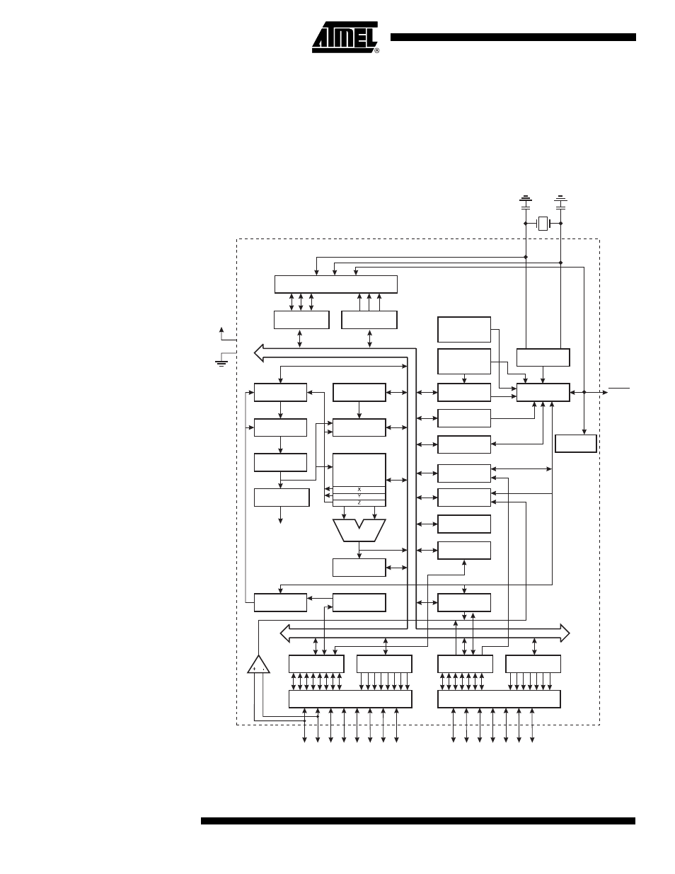
The ATtiny2313 is a low-power CMOS 8-bit microcontroller based on the AVR
enhanced RISC architecture. By executing powerful instructions in a single clock cycle,
the ATtiny2313 achieves throughputs approaching 1 MIPS per MHz allowing the system
designer to optimize power consumption versus processing speed.
Block Diagram
Figure 2. Block Diagram
PROGRAM
COUNTER
PROGRAM
FLASH
INSTRUCTION
REGISTER
GND
VCC
INSTRUCTION
DECODER
CONTROL
LINES
STACK
POINTER
SRAM
GENERAL
PURPOSE
REGISTER
ALU
STATUS
REGISTER
PROGRAMMING
LOGIC
SPI
8-BIT DATA BUS
XTAL1
XTAL2
RESET
INTERNAL
OSCILLATOR
OSCILLATOR
WATCHDOG
TIMER
TIMING AND
CONTROL
MCU CONTROL
REGISTER
MCU STATUS
REGISTER
TIMER/
COUNTERS
INTERRUPT
UNIT
EEPROM
USI
USART
ANALOG
COMP
ARA
T
O
R
DATA REGISTER
PORTB
DATA DIR.
REG. PORTB
DATA REGISTER
PORTA
DATA DIR.
REG. PORTA
PORTB DRIVERS
PB0 - PB7
PORTA DRIVERS
PA0 - PA2
DATA REGISTER
PORTD
DATA DIR.
REG. PORTD
PORTD DRIVERS
PD0 - PD6
ON-CHIP
DEBUGGER
INTERNAL
CALIBRATED
OSCILLATOR