Usart baud rate registers – ubrrl and ubrrh, Attiny2313 – Rainbow Electronics ATtiny2313 User Manual
Page 135
135
ATtiny2313
2543A–AVR–08/03
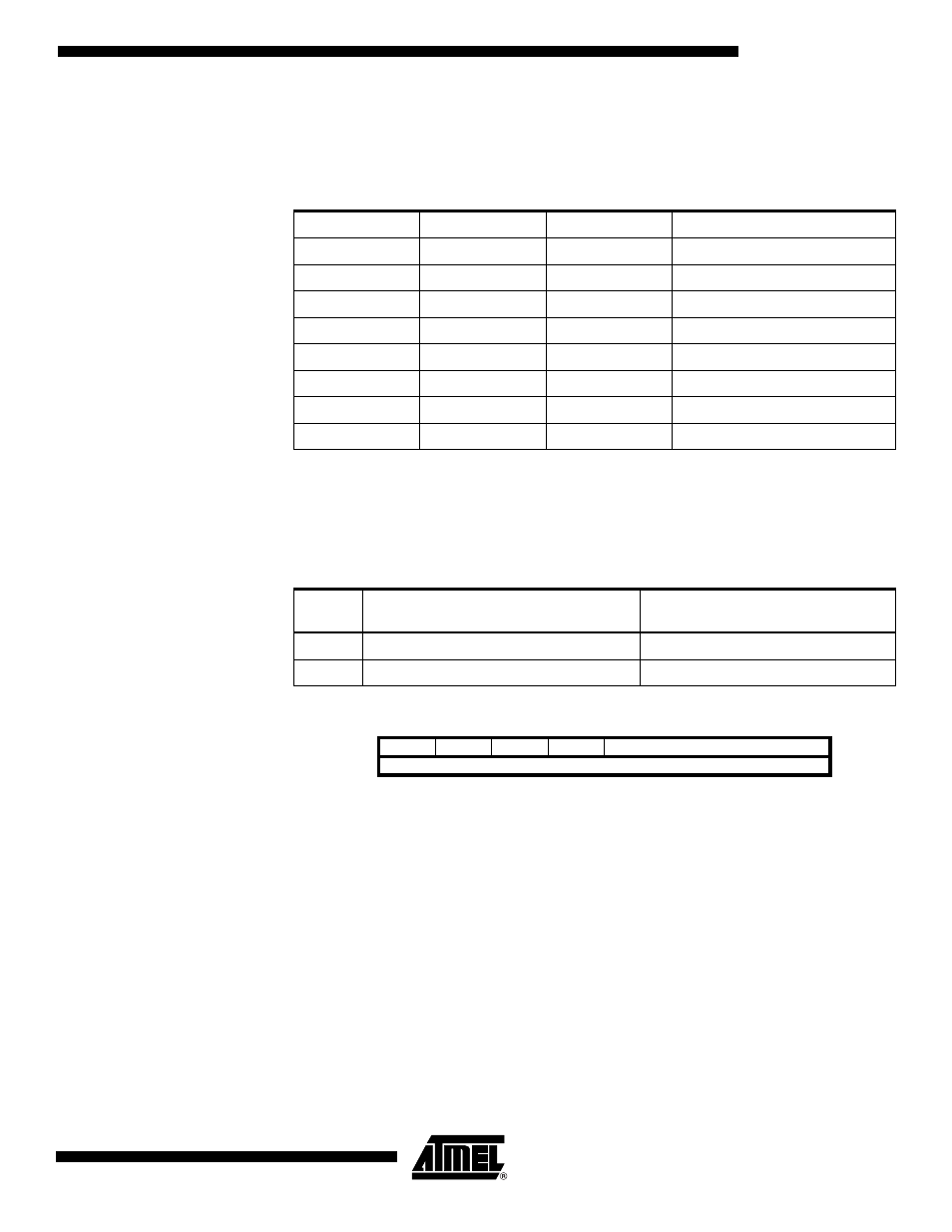
• Bit 2:1 – UCSZ1:0: Character Size
The UCSZ1:0 bits combined with the UCSZ2 bit in UCSRB sets the number of data bits
(Character SiZe) in a frame the Receiver and Transmitter use.
• Bit 0 – UCPOL: Clock Polarity
This bit is used for synchronous mode only. Write this bit to zero when asynchronous
mode is used. The UCPOL bit sets the relationship between data output change and
data input sample, and the synchronous clock (XCK).
USART Baud Rate Registers –
UBRRL and UBRRH
• Bit 15:12 – Reserved Bits
These bits are reserved for future use. For compatibility with future devices, these bit
must be written to zero when UBRRH is written.
• Bit 11:0 – UBRR11:0: USART Baud Rate Register
This is a 12-bit register which contains the USART baud rate. The UBRRH contains the
four most significant bits, and the UBRRL contains the eight least significant bits of the
USART baud rate. Ongoing transmissions by the Transmitter and Receiver will be cor-
rupted if the baud rate is changed. Writing UBRRL will trigger an immediate update of
the baud rate prescaler.
Table 55. UCSZ Bits Settings
UCSZ2
UCSZ1
UCSZ0
Character Size
0
0
0
5-bit
0
0
1
6-bit
0
1
0
7-bit
0
1
1
8-bit
1
0
0
Reserved
1
0
1
Reserved
1
1
0
Reserved
1
1
1
9-bit
Table 56. UCPOL Bit Settings
UCPOL
Transmitted Data Changed (Output of
TxD Pin)
Received Data Sampled (Input on
RxD Pin)
0
Rising XCK Edge
Falling XCK Edge
1
Falling XCK Edge
Rising XCK Edge
Bit
15
14
13
12
11
10
9
8
–
–
–
–
UBRR[11:8]
UBRRH
UBRR[7:0]
UBRRL
7
6
5
4
3
2
1
0
Read/Write
R
R
R
R
R/W
R/W
R/W
R/W
R/W
R/W
R/W
R/W
R/W
R/W
R/W
R/W
Initial Value
0
0
0
0
0
0
0
0
0
0
0
0
0
0
0
0