Power-on reset, Attiny2313 – Rainbow Electronics ATtiny2313 User Manual
Page 35
35
ATtiny2313
2543A–AVR–08/03
Notes:
1. Values are guidelines only. Actual values are TBD.
2. The Power-on Reset will not work unless the supply voltage has been below V
POT
(falling)
Power-on Reset
A Power-on Reset (POR) pulse is generated by an On-chip detection circuit. The detec-
tion level is defined in Table 15. The POR is activated whenever V
CC
is below the
detection level. The POR circuit can be used to trigger the start-up Reset, as well as to
detect a failure in supply voltage.
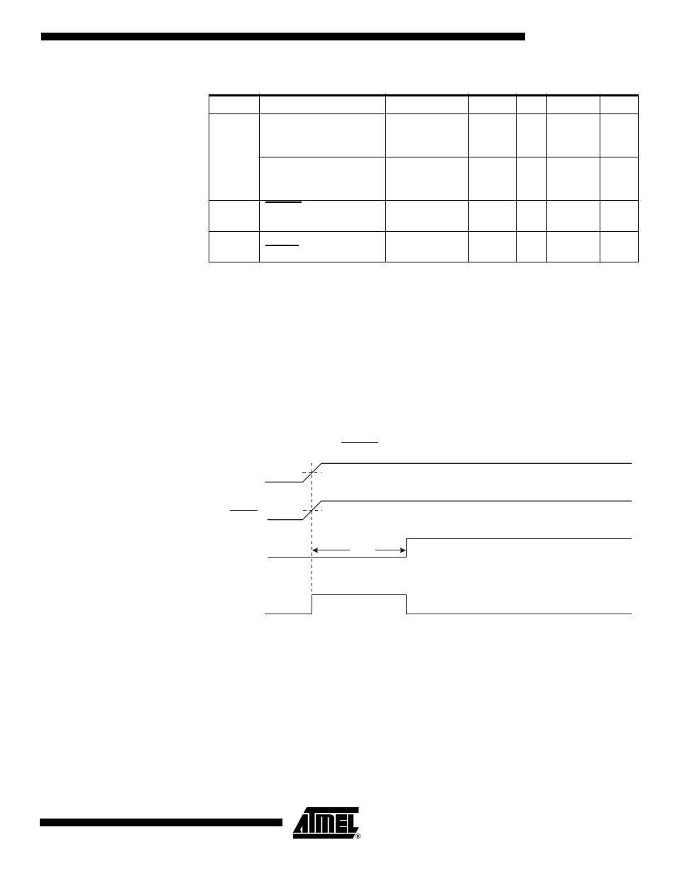
A Power-on Reset (POR) circuit ensures that the device is reset from Power-on. Reach-
ing the Power-on Reset threshold voltage invokes the delay counter, which determines
how long the device is kept in RESET after V
CC
rise. The RESET signal is activated
again, without any delay, when V
CC
decreases below the detection level.
Figure 15. MCU Start-up, RESET Tied to V
CC
Table 15. Reset Characteristics
(1)
Symbol
Parameter
Condition
Min
Typ
Max
Units
V
POT
Power-on Reset
Threshold Voltage
(rising)
T
A
= -40 - 85
°
C
1.2
V
Power-on Reset
Threshold Voltage
(falling)
(2)
T
A
= -40 - 85
°
C
1.1
V
V
RST
RESET Pin Threshold
Voltage
V
CC
= 3V
0.2 V
CC
0.85 V
CC
V
t
RST
Minimum pulse width on
RESET Pin
V
CC
= 3V
900
ns
V
RESET
TIME-OUT
INTERNAL
RESET
t
TOUT
V
POT
V
RST
CC