Ra01 – Rainbow Electronics RA01 User Manual
Page 6
RA01
Version: 1.0 Date: 10/8/2008
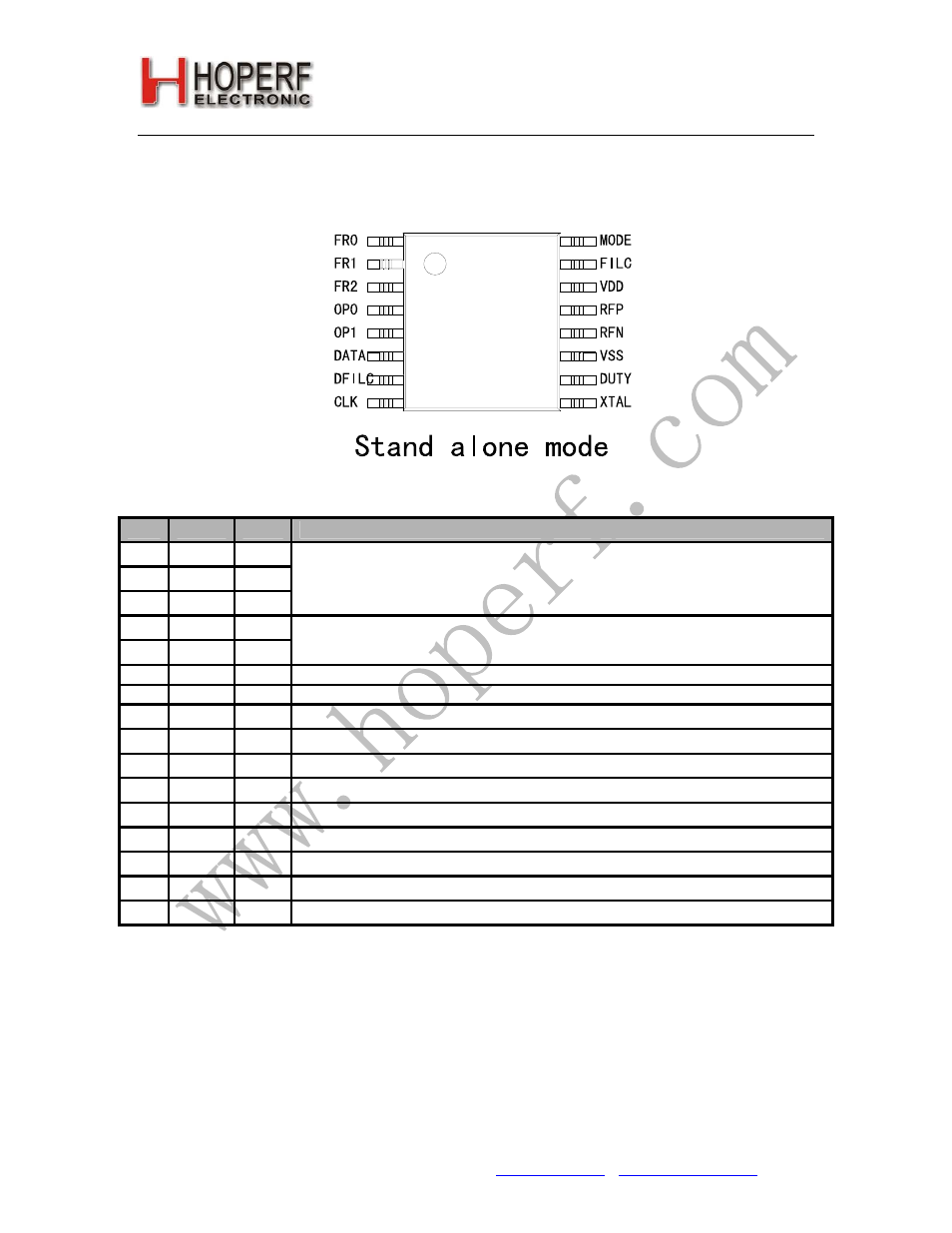
Standalone Mode
RA01
Pin
Name
Type Function
1 FR0 DI
2 FR1 DI
3 FR2 DI
Receiving frequency setting inputs
4 OP0 DO
5 OP1 DO
Operation mode select:
00: Shutdown, 01:433MHz band, 10: 868MHz band, 11: Reserved
6 DATA DO
Demodulated data output
7 DFILC AIO
Data filter capacitor connection (See
Data Filter Command
for details)
8 CLK DO
Microcontroller clock output (optional)
9 XTAL AIO
Reference crystal connection
10 DUTY DI
Low duty cycle rx mode
11 VSS S
Supply ground reference
12 RFN AI
Differential RF (antenna) input
13 RFP AI
Differential RF (antenna) input
14 VDD S
Positive supply voltage
15 FILC AIO
Filter capacitor connection (See
Demodulator Setting Command
for details)
16 MODE DI
Mode select input. Low=stand alone mode
Tel: +86-755-82973805 Fax: +86-755-82973550 E-mail: [email protected] http://www.hoperf.com
6
- RC2000 (2 pages)
- Т7023 (12 pages)
- Т7024 (20 pages)
- RC2200 (17 pages)
- RF01 (26 pages)
- RC1090 (17 pages)
- U3741BM (32 pages)
- U3742BM (32 pages)
- RAM01 (7 pages)
- RF22 (92 pages)
- RC1180-MBUS (28 pages)
- RFM01 (8 pages)
- RF12B (36 pages)
- RC1290 (17 pages)
- RC2300-ZNM (1 page)
- RF12 (31 pages)
- T48C862-R3 (107 pages)
- RF02 (24 pages)
- T48C862-R8 (107 pages)
- RFM12 (10 pages)
- U3745BM (29 pages)
- T5744 (19 pages)
- RFM12B (10 pages)
- U2745B (9 pages)
- T48C862-R4 (107 pages)
- T5754 (11 pages)
- U2741B (9 pages)
- RFM02 (8 pages)
- RC2100 (22 pages)
- RF модули диапазона ISM (4 pages)
- T5761 (35 pages)
- BTM -17х (5 pages)
- ATA8401 (12 pages)
- BTM -22х (7 pages)
- AT86RF231 (180 pages)
- ATA5575M1 (7 pages)
- AT88RF1354 (50 pages)
- ATA5812 (90 pages)
- AT86RF401 (50 pages)
- AT76C551 (77 pages)
- BTM -250 (6 pages)
- AT75C310 (132 pages)
- AT75C320 (13 pages)
- BTM -140 (6 pages)