Ra01, Data rate command, Output and fifo mode command – Rainbow Electronics RA01 User Manual
Page 13
RA01
Version: 1.0 Date: 10/8/2008
Tel: +86-755-82973805 Fax: +86-755-82973550 E-mail: [email protected] http://www.hoperf.com
13
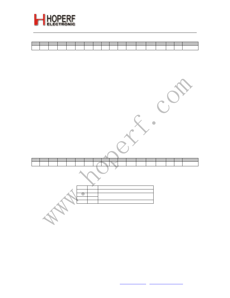
8. Data Rate Command
bit
15
14
13
12
11
10
9
8
7
6
5
4
3
2
1
0
POR
1
1
0
0
1
0
0
0
cs
r6
r5
r4
r3
r2
r1
r0
C813h
The expected bit rate of the received data stream is determined by the 7-bit value R (bits
r6
to
r0
) and the 1 bit
cs
.
BR = 10 MHz / 29 / (R+1) / (
1 + cs
*7)
In the receiver set R according the next function:
R= (10 MHz / 29 /(
1 + cs
*7)/ BR) – 1
Apart from setting custom values, the standard bit rates from 600 bps to 115.2 kbps can be approximated with small
error.
Data rate accuracy requirements:
Clock recovery in slow mode:
Δ
BR/BR < 1/(29*N
bit
) Clock recovery in fast mode:
Δ
BR/BR < 3/(29*N
bit
)
BR is the bit rate set in the receiver and
Δ
BR is bit rate difference between the transmitter and the receiver. N
bit
is the
maximal number of consecutive ones or zeros in the data stream. It is recommended for long data packets to
include enough 1/0 and 0/1 transitions, and be careful to use the same division ratio in the receiver and in the
transmitter.
Δ
BR is a theoretical limit for the clock recovery circuit. Clock recovery will not work above this limit. The clock
recovery circuit will always operate below this limit independently from process, temperature, or Vdd condition.
e.g. Supposing a maximum length of consecutive zeros or ones in the data stream is less than 5 bits, the necessary
relative accuracy is 0.68% in slow mode and 2.1% in fast mode.
9. Output and FIFO Mode Command
bit
15
14
13
12
11
10
9
8
7
6
5
4
3
2
1
0
POR
1
1
0
0
1
1
1
0
f3
f2
f1
f0
s1
s0
ff
fe
CE87h
Bit 7-4 <
f3
:
f0
>: FIFO IT level. The FIFO generates IT when number of the received data bits reaches this level.
Bit 3-2 <
s1
:
s0
>: Select the input of the FIFO fill start condition:
s1
s0
FIFO fill starts
0
0
VDI
0
1
1
0
Sync. Word
1
1
Always fill
Note: VDI (Valid Data Indicator) see further details in
Receiver Setting Command
, Synchron word in microcontroller
mode is 2DD4h.
Bit 1 <
ff
>: Enables FIFO fill after synchron word reception. FIFO fill stops when this bit is cleared.
Bit 0 <
fe
>: Enables the 64 bit deep FIFO mode. To clear the counter of the FIFO, it has to be set to zero.
Note: To restart the synchron word reception, bit 1 should be cleared and set. This action will initialize the FIFO and
clear its content.
Bit 0 modifies the function of DATA pad and DCLK pad. The DATA pad will become input (nFFS) if
fe
is set to 1.
If the chip is used in FIFO mode, do not allow this to be a floating input.