Ra01, Data filter command – Rainbow Electronics RA01 User Manual
Page 12
RA01
Version: 1.0 Date: 10/8/2008
Tel: +86-755-82973805 Fax: +86-755-82973550 E-mail: [email protected] http://www.hoperf.com
12
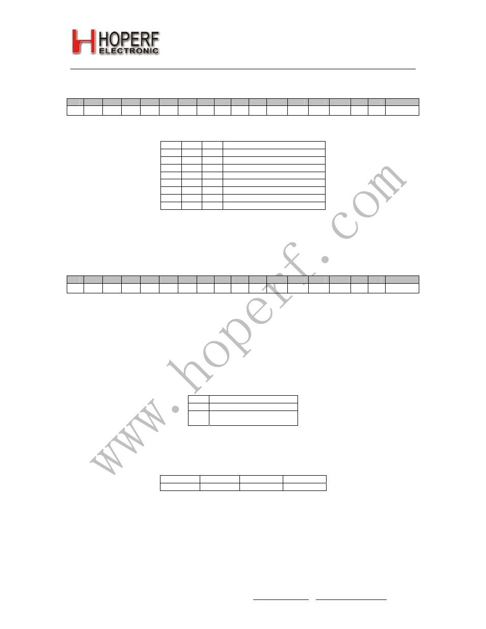
6. Low Battery Detector and Microcontroller Clock Divider Command
bit
15
14
13
12
11
10
9
8
7
6
5
4
3
2
1
0
POR
1
1
0
0
0
0
1
0
d2
d1
d0
elfc
t3
t2
t1
t0
C213h
Bit 7-5
d2
d1
d0
Clock Output Frequency [MHz]
0
0
0
1
0
0
1
1.25
0
1
0
1.66
0
1
1
2
1
0
0
2.5
1
0
1
3.33
1
1
0
5
1
1
1
10
Bit 4 <
elfc
>: Enables low frequency (32 kHz) microcontroller output clock during sleep mode.
Bits 3-0
lb
of the detector:
V
lb
= 2.0 V + T * 0.1 V
7. Data Filter Command
bit
15
14
13
12
11
10
9
8
7
6
5
4
3
2
1
0
POR
1
1
0
0
0
1
0
0
al
ml
dsfi
sf
ewi
srt
1
0
C462h
Bit 7 <
al
>: Clock recovery (CR) auto lock control if set. It means that the CR start in fast mode after locking it
automatically switches to slow mode.
Bit 6 <
ml
>: Clock recovery lock control 1: fast mode, fast attack and fast release - 0: slow mode, slow attack and
slow release
Using the slower one requires more accurate bit timing (see
Data Rate Command
).
Bit 5 <
dsfi
>: Disables autosleep on FIFO interrupt if set to 1.
Bit 4 <
sf
>: Selects the type of the data filter:
sf
Filter Type
0
Digital Filter
1
Analog Filter with external
capacitor on pin7
Digital: this is a digital realization of an analog RC filter followed by a comparator with hysteresis. The time constant
is automatically adjusted to the bit rate defined by the
Data Rate Command
.
The table shows the optimal filter capacitor values for different data rates
4.8 kbps
9.6 kbps
19.2 kbps
38.4 kbps
6.8 nF
3.3 nF
1.5 nF
680 pF
Note: If analog RC filter is selected the internal clock recovery circuit and the FIFO can not be used.
Bit 3 <
ewi
>: Enables the automatic wake-up on any interrupt event.
Bit 2