Ra01, Frequency setting command, Receiver setting command – Rainbow Electronics RA01 User Manual
Page 11: Wake-up timer command, Extended wake-up timer command
RA01
Version: 1.0 Date: 10/8/2008
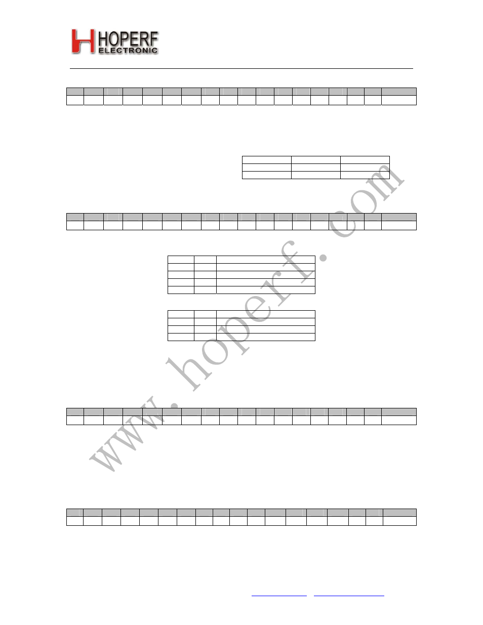
2. Frequency Setting Command
bit
15
14
13
12
11
10
9
8
7
6
5
4
3
2
1
0
POR
1
0
1
0
f11
f10
f9
f8
f7
f6
f5
f4
f3
f2
f1
f0
AD57h
The 12-bit Frequency Setting Command <f11 :
f0> has the value F. The value F should be in the
range of 96 and 3903. When F is out of range, the
previous value is kept. The synthesizer center
frequency f
0
can be calculated as:
f
0
= R * 10 MHz * (C + F/4000)
The constant C is determined by the selected
band as:
Band [MHz]
R
C
433
4
5
868
8
10
3. Receiver Setting Command
bit
15
14
13
12
11
10
9
8
7
6
5
4
3
2
1
0
POR
1
1
0
0
0
0
0
0
d1
d0
g1
g0
sq
0
0
en
C080h
Bit 7-6 <
d1:d0
>: Select the VDI (valid data indicator) signal:
d1
d0
VDI output
0
0
RSSI or Clock Recovery Lock
0
1
RSSI
1
0
Clock Recovery Lock
1
1
Always High
Bit 5-4 <
g1:g0
>: Set the LNA gain:
g1
g0
G
LNA
(dB relative to max. G)
0
X
Automatic Gain Switch
1
0
-32
1
1
0
Bit 3
Bit 0 <
en
>: Enables the whole receiver chain and crystal ocsillator when set. Enable/disable of the wake-up timer
and the low battery detector are not affected by this setting.
4. Wake-up Timer Command
bit
15
14
13
12
11
10
9
8
7
6
5
4
3
2
1
0
POR
1
1
1
0
r3
r2
r1
r0
m7
m6
m5
m4
m3
m2
m1
m0
E196h
The wake-up time period can be calculated by M <
m13
:
m0
> , R <
r3
:
r0
> and D <
d1
:
d0
>:
T
wake-up
= M * 2
R-D
ms
Note: The wake-up timer generates interrupts continuously at the programmed interval while the
et
bit is set.
5. Extended Wake-up Timer Command
bit
15
14
13
12
11
10
9
8
7
6
5
4
3
2
1
0
POR
1
1
0
0
0
0
1
1
d1
d0
m13
m12
m11
m10
m9
m8
C300h
These bits can be used for further fine adjustment of the wake-up timer. The explanation of the bits can be found
above.
Tel: +86-755-82973805 Fax: +86-755-82973550 E-mail: [email protected] http://www.hoperf.com
11