Ra01, Extended features command, Low duty cycle command – Rainbow Electronics RA01 User Manual
Page 14: Demodulator setting command
RA01
Version: 1.0 Date: 10/8/2008
Tel: +86-755-82973805 Fax: +86-755-82973550 E-mail: [email protected] http://www.hoperf.com
14
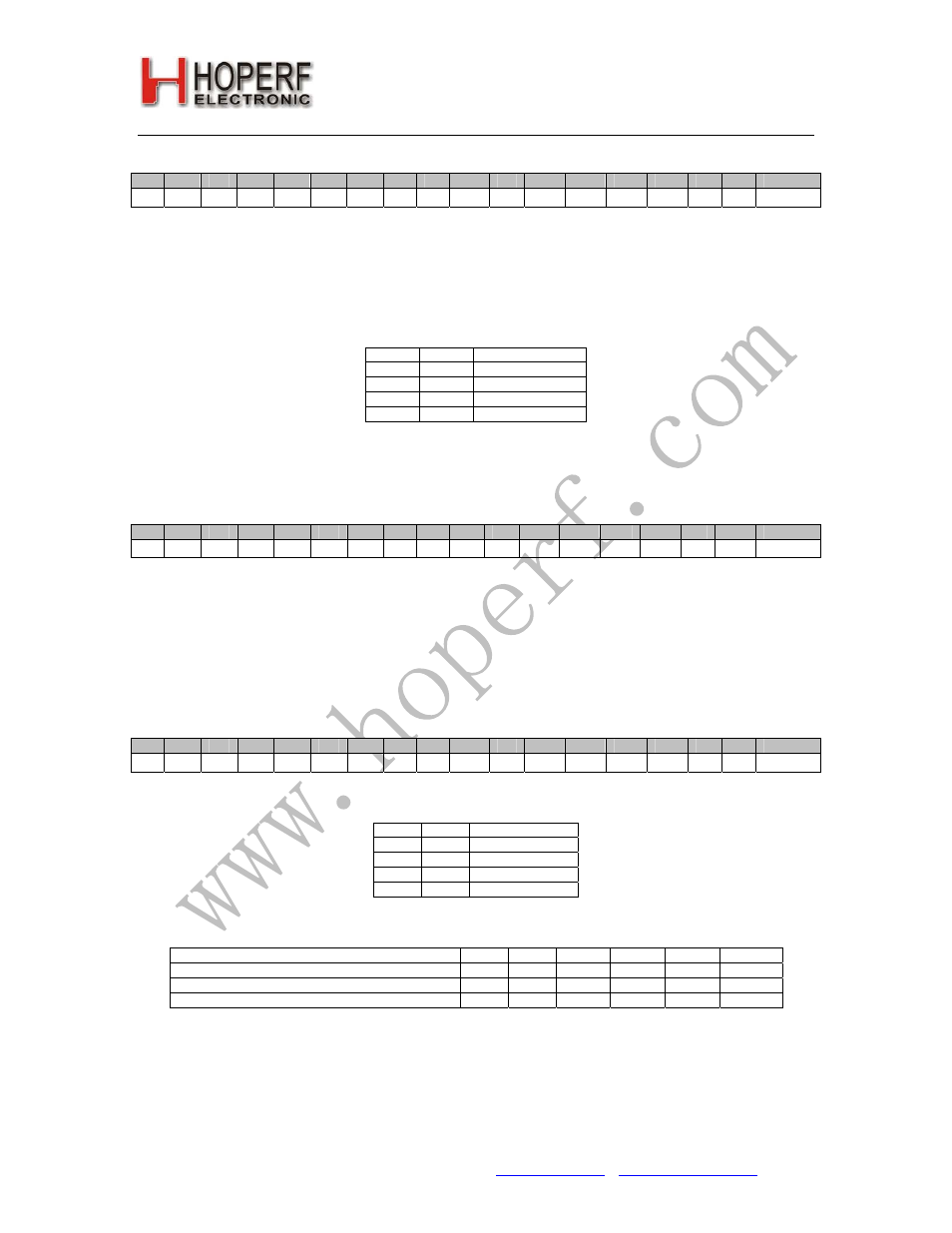
10. Extended Features Command
bit
15
14
13
12
11
10
9
8
7
6
5
4
3
2
1
0
POR
1
0
1
1
0
0
0
0
exlp
ctls
0
dcal
bw1
bw0
f5
f4
B0CAh
Bit 7 <
exlp
>: Enables low power mode for the crystal oscillator.
Bit 6 <
ctls
>: Clock tail selection bit. Setting this bit selects 512 bit long clock tail instead of the default 128 bit length.
Bit 4 <
dcal
>: Disables the wake-up timer auto calibration.
Bit 3-2 <
bw1:bw0
>: Select the bandwidth of the PLL.
bw1
bw0
PLL bandwidth
0
0
15 kHz
0
1
30 kHz
1
0
60 kHz
1
1
120 kHz
Bit 1-0 <
f5:f4
>: Upper two bits for selecting the 64 bit FIFO IT level together with the
f3-f0
bits in the Output and
FIFO Mode Command.
11. Low Duty Cycle Command
bit
15
14
13
12
11
10
9
8
7
6
5
4
3
2
1
0
POR
1
0
1
1
0
0
0
0
d6
d5
d4
d3
d2
d1
d0
enld
B0CAh
Bit 7-1 <
d6:d1
>: The Duty-Cycle can be calculated by using D (
d6
to
d0
) and M. (M is parameter in a
Wake-Up
Timer Command
.)
Duty-Cycle= (D * 2 +1) / M *100%
Bit 0 <
enld
>: Enables the low duty cycle operation of the receiver.
12. Demodulator Setting Command
bit
15
14
13
12
11
10
9
8
7
6
5
4
3
2
1
0
POR
1
0
1
1
0
0
0
0
tc1
tc0
0
0
0
0
0
0
D000h
Bit 7-6 <
tc1:tc0
>: Select the time constant of the demodulator
tc1
tc0
Time constant
0
0
Fast
1
1
Middle
1
0
Slow
1
1
Reserved
The table shows the optimal filter capacitor values for different popular data rates:
Data Rate [kbps] Manchester
2.4
4.8
9.6
19.2
38.4
>38.4
Data Rate [kbps] NRZ
-
2.4
4.8
9.6
19.2
>19.2
Recommended Capacitor on pin15 ( FILC) [pF]
330
330
220
100
27
0
Optimal
Slow
Slow
Middle
Middle
Fast
Fast
Note: Manchester coding doubles the bandwidth requirement compared to NRZ.