Ra01, Pin definitions, Controller mode – Rainbow Electronics RA01 User Manual
Page 4
RA01
Version: 1.0 Date: 10/8/2008
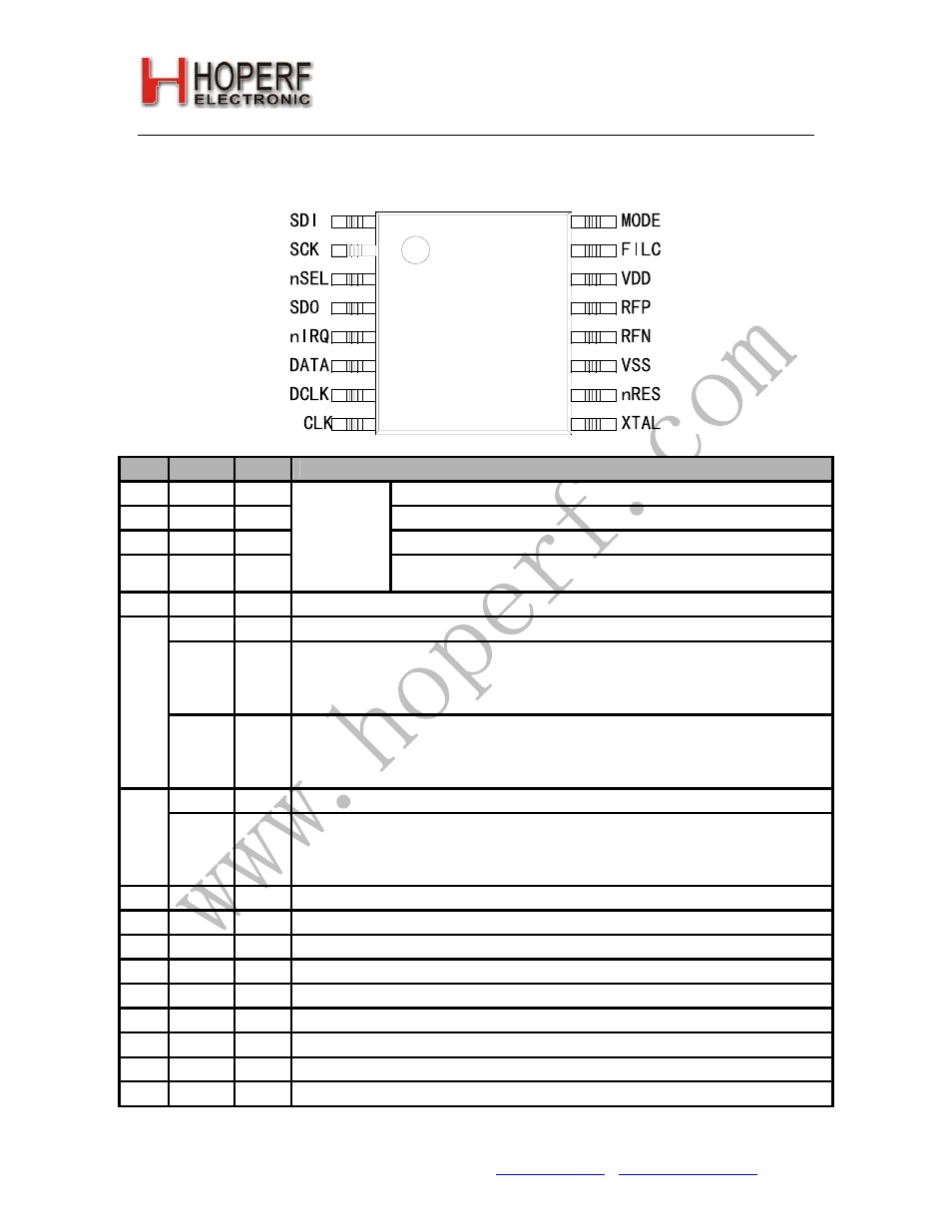
PIN DEFINITIONS
A=analog, D=digital, S=supply, I=input, O=output, IO=input / output
Controller Mode
RA01
Pin
Name
Type Function
1 SDI DI
Serial
data
input
2 SCK DI
Serial
clock
input
3
nSEL
DI
Select input (active low)
4 SDO DO
SPI
interface
Serial data output (tri-state if SPI bus is not selected, internal
bus-hold cell)
5 nIRQ DO
Interrupt request output (active low)
DATA DO
Demodulated data output
nFFS DI
FIFO direct select input, with internal pull-up.
Conditions:
ef
= high in
Output and FIFO mode Command.
sf = low
in the
Data Filter Command
.
Note:
6 Value of the internal pull up resistor is 120 kOhm.
6
DFILC AIO
Data Filter Capacitor connection
Conditions:
ef
= low in
Output and FIFO mode Command.
sf =
high in the
Data Filter Command
.
Note:
If this bit is set the internal clock recovery and the FIFO is not usable.
DCLK DO
Recovered data clock output for bit sampling
7
FFIT DO
FIFO interrupt output
High when the number of the bits in the RX FIFO has reached the preprogrammed limit.
Conditions:
ef
= high in
Output and FIFO mode Command.
sf =
low in the
Data Filter Command
.
8 CLK DO
Microcontroller clock output (optional)
9 XTAL AIO
Reference crystal connection
10 nRES DO
Power-on reset output (active low, optional)
11 VSS S
Supply ground reference
12 RFN AI
Differential RF (antenna) input
13 RFP AI
Differential RF (antenna) input
14 VDD S
Positive supply voltage
15 FILC AIO
Filter capacitor connection (See
Demodulator Setting Command
for details)
16 MODE DI
Mode select input. High=microcontroller mode
Tel: +86-755-82973805 Fax: +86-755-82973550 E-mail: [email protected] http://www.hoperf.com
4