Rainbow Electronics MAX7033 User Manual
Page 10
The off-chip inductive degeneration is achieved by
connecting an inductor from LNASRC to AGND. This
inductor sets the real part of the input impedance at
LNAIN, allowing for a more flexible input impedance
match, such as a typical PC board trace antenna. A
nominal value for this inductor with a 50
Ω input imped-
ance is 15nH, but is affected by PC board trace.
The LC tank filter connected to LNAOUT comprises L3
and C2 (see the Typical Application Circuit). Select L3
and C2 to resonate at the desired RF input frequency.
The resonant frequency is given by:
where:
L
TOTAL
= L3 + L
PARASITICS
.
C
TOTAL
= C2 + C
PARASITICS
.
L
PARASITICS
and C
PARASITICS
include inductance and
capacitance of the PC board traces, package pins,
mixer input impedance, LNA output impedance, etc.
These parasitics at high frequencies cannot be
ignored, and can have a dramatic effect on the tank fil-
ter center frequency. Lab experimentation should be
done to optimize the center frequency of the tank.
Automatic Gain Control
When the AC pin is low, the automatic gain-control
(AGC) circuit monitors the RSSI output. As the RSSI
output reaches 1.98V, which corresponds to RF input
level of -62dBm, the AGC switches on the LNA gain
reduction resistor. The resistor reduces the LNA gain
by 35dB, thereby reducing the RSSI output by about
500mV. The LNA resumes high-gain mode when the
RSSI level drops back below 1.39V (approximately
-70dBm at RF input) for 1ms. The AGC has a hysteresis
of 8dB. With the AGC function, the MAX7033 can reli-
ably produce an ASK output for RF input levels up to
0dBm with modulation depth of 18dB.
When the AC pin is high and SHDN goes high, the
AGC circuit is disabled and the LNA is always in high-
gain mode. The AGC function can be resumed by
bringing the AC pin low when SHDN is high.
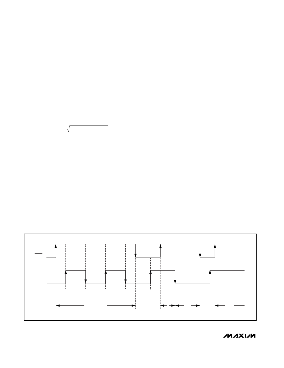
The MAX7033 features an AGC lock function that is
asserted when the level at the AC pin transitions from
low to high while SHDN is high. Locking the AGC locks
the LNA in the current gain state. As shown in Figure 1,
the AGC lock function can be enabled or disabled as
long as the SHDN pin is high. Changing the state of AC
when SHDN is low has no effect.
Mixer
A unique feature of the MAX7033 is the integrated
image rejection of the mixer. This device eliminates the
need for a costly front-end SAW filter for most applica-
tions. Advantages of not using a SAW filter are
increased sensitivity, simplified antenna matching, less
board space, and lower cost.
The mixer cell is a pair of double balanced mixers that
perform an IQ downconversion of the RF input to the
10.7MHz IF from a low-side injected LO (i.e., f
LO
= f
RF
-
f
IF
). The image-rejection circuit then combines these
signals to achieve 44dB of image rejection. Low-side
f
L
C
RF
TOTAL
TOTAL
=
×
1
2
π
MAX7033
315MHz/433MHz ASK Superheterodyne
Receiver with AGC Lock
10
______________________________________________________________________________________
AGC
LOCK
AGC
UNLOCK
AGC
LOCK
AGC
UNLOCK
NO
EFFECT
NO
EFFECT
SHDN
PIN
AC PIN
V
IL
V
IH
V
IH
V
IL
NO
EFFECT
AGC ENABLED
AGC
ENABLED
AGC
DISABLED
AGC
DISABLED
Figure 1. AGC Lock Activation Cycles