Ac electrical characteristics (continued) – Rainbow Electronics MAX7034 User Manual
Page 4
MAX7034
315MHz/434MHz ASK Superheterodyne
Receiver
4
_______________________________________________________________________________________
Note 1: 100% tested at T
A
= +125°C. Guaranteed by design and characterization over entire temperature range.
Note 2: IRSEL is internally set to 375MHz IR mode. It can be left open when the 375MHz image-rejection setting is desired. Bypass
to AGND with a 1nF capacitor in a noisy environment.
Note 3: Peak power level. BER = 2 x 10
-3
, Manchester encoded, data rate = 4kbps, IF bandwidth = 280kHz.
Note 4: The voltage conversion gain is measured with the LNA input matching inductor and the LNA/Mixer resonator in place, and
does not include the IF filter insertion loss.
Note 5: Crystal oscillator frequency for other RF carrier frequency within the 300MHz to 450MHz range is (f
RF
- 10.7MHz)/64 for
XTALSEL = 0V, and (f
RF
- 10.7MHz)/32 for XTALSEL = DV
DD
.
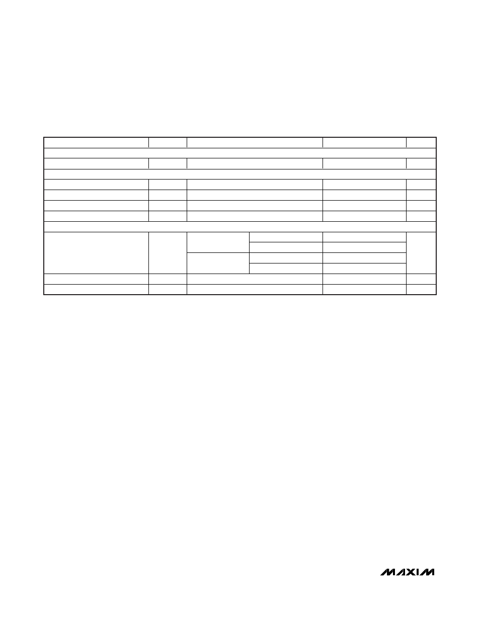
PARAMETER
SYMBOL
CONDITIONS
MIN
TYP
MAX
UNITS
DATA FILTER
Maximum Bandwidth
50
kHz
DATA SLICER
Comparator Bandwidth
100
kHz
Maximum Load Capacitance
C
LOAD
10
pF
Output High Voltage
V
VDD5
V
Output Low Voltage
0
V
CRYSTAL OSCILLATOR
V
XTALSEL
= 0V
6.6128
f
RF
= 433.92MHz
V
XTALSEL
= DV
DD
13.2256
V
XTALSEL
= 0V
4.7547
Crystal Frequency (Note 5)
f
XTAL
f
RF
= 315MHz
V
XTALSEL
= DV
DD
9.5094
MHz
Crystal Tolerance
50
ppm
Input Capacitance
From each pin to ground
6.2
pF
AC ELECTRICAL CHARACTERISTICS (continued)
(
Typical Application Circuit, V
VDD5
= +4.5V to +5.5V, all RF inputs are referenced to 50Ω, f
RF
= 433.92MHz, T
A
= -40°C to +125°C,
unless otherwise noted. Typical values are at V
VDD5
= +5.0V and T
A
= +25°C.) (Note 1)