Peak detector, Layout considerations – Rainbow Electronics MAX7034 User Manual
Page 11
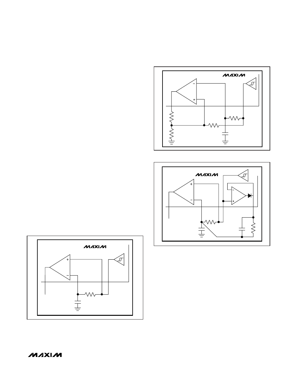
Peak Detector
The peak-detector output (PDOUT), in conjunction with
an external RC filter, creates a DC output voltage equal
to the peak value of the data signal. The resistor pro-
vides a path for the capacitor to discharge, allowing the
peak detector to dynamically follow peak changes of
the data-filter output voltage. For faster data slicer
response, use the circuit shown in Figure 4. For more
details on hysteresis and peak-detector applications,
refer to Maxim Application Note 3671,
Data Slicing
Techniques for UHF ASK Receivers
.
Layout Considerations
A properly designed PCB is an essential part of any
RF/microwave circuit. On high-frequency inputs and
outputs, use controlled-impedance lines and keep them
as short as possible to minimize losses and radiation.
At high frequencies, trace lengths that are on the order
of
λ/10 or longer act as antennas.
Keeping the traces short also reduces parasitic induc-
tance. Generally, 1 inch of a PCB trace adds about
20nH of parasitic inductance. The parasitic inductance
can have a dramatic effect on the effective inductance
of a passive component. For example, a 0.5 inch trace
connecting a 100nH inductor adds an extra 10nH of
inductance or 10%.
To reduce the parasitic inductance, use wider traces
and a solid ground or power plane below the signal
traces. Also, use low-inductance connections to ground
on all GND pins, and place decoupling capacitors
close to all V
DD
connections.
MAX7034
315MHz/434MHz ASK Superheterodyne
Receiver
______________________________________________________________________________________
11
DATA
SLICER
R1
25
DATAOUT
20
DSN
19
DFO
23
DSP
C4
MAX7034
DATA
SLICER
R3
R1
R2
R4
25
DATAOUT
*OPTIONAL
23
DSP
19
DFO
20
DSN
C4
MAX7034
Figure 3. Generating Data Slicer Hysteresis
DATA
SLICER
25k
Ω
25
DATAOUT
20
DSN
19
DFO
26
PDOUT
23
DSP
MAX7034
47nF
Figure 4. Using PDOUT for Faster Startup
Figure 2. Generating Data Slicer Threshold