Moog Music Taurus 3 Bass Pedals User Manual
Page 36
Page 38
Taurus 3 User’s Manual - The User Interface
Page 39
Taurus 3 User’s Manual - The User Interface
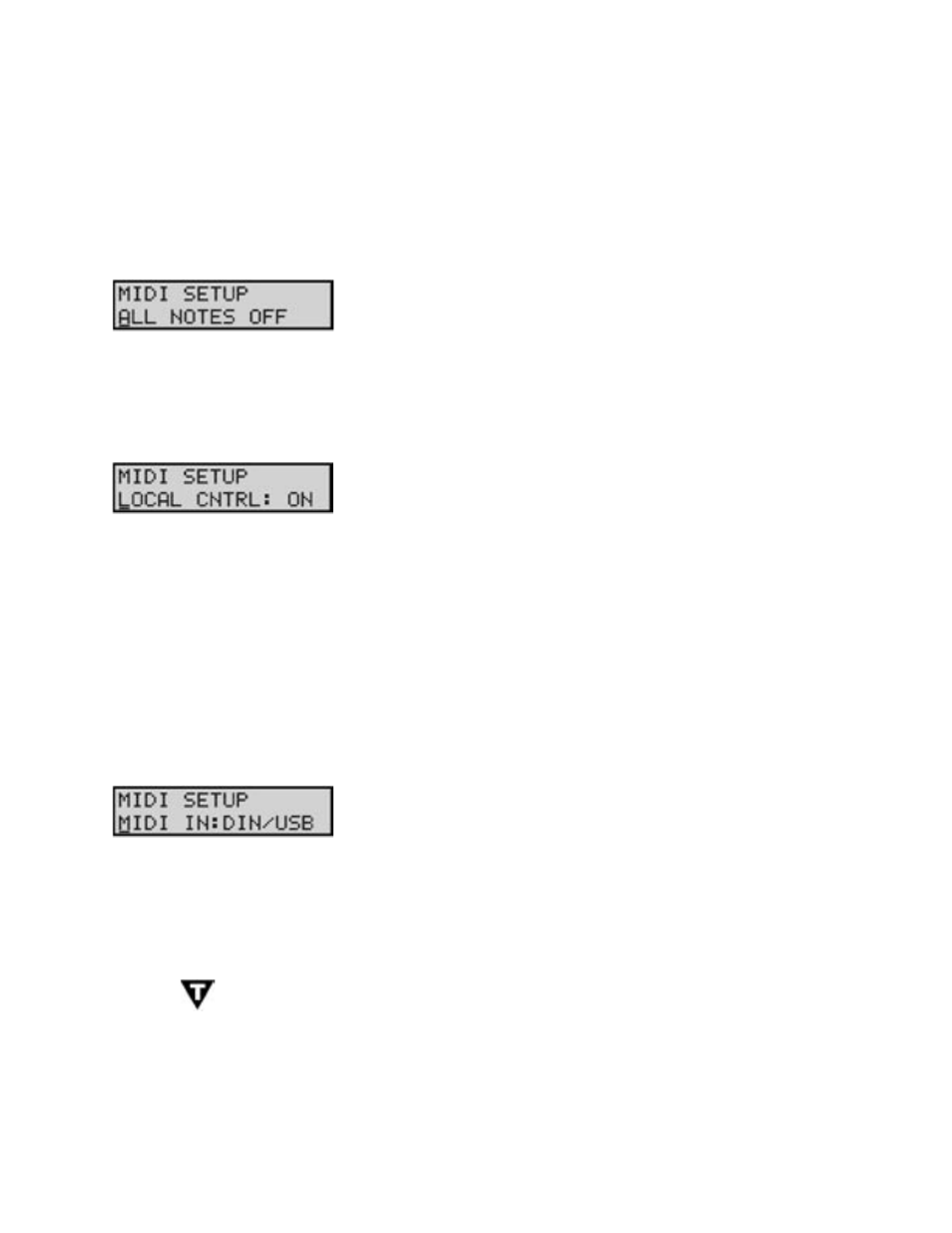
D. MIDI Setup Menus
MIDI Setup menus are used to select the T3 MIDI options. To enable MIDI Setup menus, press the CUR-
SOR button. This will highlight the menu options shown on the second line of the display. Once highlighted,
use the VALUE knob to scroll through the menus.
Allows you to issue an ‘All Notes Off ’ message to the MIDI output, shut-
ting off all active notes on the T3 and/or any attached MIDI tone modules
or keyboards. This command is the equivalent of a MIDI panic button
used to silence stuck notes. To issue the command, simply press the
STORE button (you do not have to enable this menu with the CURSOR
button).
Allows you to turn control of the T3’s synth engine ON or OFF locally.
When set to ‘ON’, the pedalboard, footwheels, and front panel controls
affect the internal sound engine, as well as generate MIDI commands
depending on the MIDI routing settings. When set to ‘OFF’, the pedal-
board, footwheels and panel controls no longer affect the sound engine,
but will still send MIDI commands. Note that a setting of ‘OFF’ will also
prevent double triggering in the event you are using a MIDI sequencer
with both the MIDI IN and MIDI OUT connected, and the sequencer is
echoing MIDI data back to the T3. To change the Local Control setting,
use the CURSOR button to highlight the control value, then use the
VALUE knob to change the setting.
Values: ON, OFF;
the default is ON
Allows you to select the MIDI input connection. Since the T3 offers
both MIDI DIN and USB connections, several input options are pos-
sible. To specify the MIDI input connection, use the CURSOR button
to highlight the input selection, then use the VALUE knob to select the
desired input.
Values: NONE, DIN, USB, DIN/USB; the default is DIN/USB
TECH NOTE: ‘DIN’ is an abbreviation for ‘Deutsches Institut für Normung’ (the German
Institute for Standardization). ‘DIN connectors’ commonly refer to a family of circular connec-
tors that were standardized by DIN for commercial electronic use. When the MIDI standard
was released in 1983, it specified a 5-pin DIN connector as the standard hardware intercon-
nection, thus the ‘MIDI DIN’ connector.
ALL NOTES OFF:
LOCAL CONTROL:
MIDI INPUT: