Access door platform, Figure #44 – Grain Systems PNEG-366 User Manual
Page 36
Grain Systems, Inc. Assumption, Ill.
36
18' Autoflow
REV. 11-20-96
2
3
1
11
10
6
4
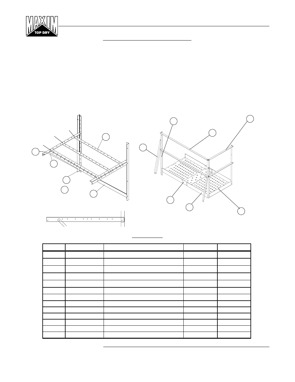
IMPORTANT: Position support
as shown for proper fit.
Before assembly of any platform, read the entire instructions to assure proper placement and assembly.
Refer to Figure #43 for proper location of access door platform. Begin by assembling the access door platform support
frame using 5/16" x 3/4" truss head bolts and nuts. When attaching platform vertical support to bin sidewall field drill
(16) 3/8" diameter holes for each support spaced every 4". Be sure and use 5/16" x 3/4" bin bolt on vertical support
to sidewall. Special attention should be taken when assembling the platform support that the support brace is placed
correctly.
Now proceed to the platform floor. Align holes on platform floor with holes on platform support and bolt together using
5/16" x 3/4" truss head bolt and nuts. Next, assemble handrail posts, handrails, and handrail braces.
ACCESS DOOR PLATFORM
8
13
&
5
7
5
11th hole
Platform Support
TDP-5009
Figure #44
Key
Part No.
Description
Quantity
Weight
1
LS-371
Platform Vertical Angle 42"
3
11.38
2
TDP-5000
Handrail 59"
2
10.15
3
TDP-5002
Handrail 30"
2
10.15
4
TDP-5003
Handrail Brace 36.29/32"
2
6.34
5
TDP-5005
Floor Brace 58.1/2"
3
26.11
6
TDP-5006
Platform Floor 37.7/8"
2
38.23
7
TDP-5007
Support Brace 50.21/32"
2
15.08
8
TDP-5008
Sidewall Brace 58"
2
19.65
9
TDP-5009
Platform Support 43.1/2"
2
12.95
10
TDP-5010
Platform Floor Splice 37.1/2"
1
6.24
11
TDP-5011
Platform Toe Plate 29.3/4"
1
3.29
12
TDP-5014
Access Door Package Hardware
1
5.41
13
TDP-5008N
Sidewall Brace 2.66"
2
16.61
7th hole
3rd hole
9