3 instrument connection, 1 vvo directly on the sensor, 2 vvo on the 4 … 20 ma-line – VEGA VVO VEGA Visual Operating User Manual
Page 6: 3 vvo on the vbus-line, Instrument connection, Connection possibility via vegaconnect 2 on hart
6
VEGA Visual Operating
+
-
VEGACONNECT 2
to sensor
R = 100
W
Instrument connection
3 Instrument connection
3.1 VVO directly on the sensor
VEGACONNECT
2
VEGACONNECT
2
For connection of the PC directly to the sen-
sor, a VEGACONNECT 2 should be con-
nected as adapter. 2 mm-sockets are
provided on all communication capable
VEGA-sensors, where the two-wire line of
VEGACONNECT 2 can be inserted.
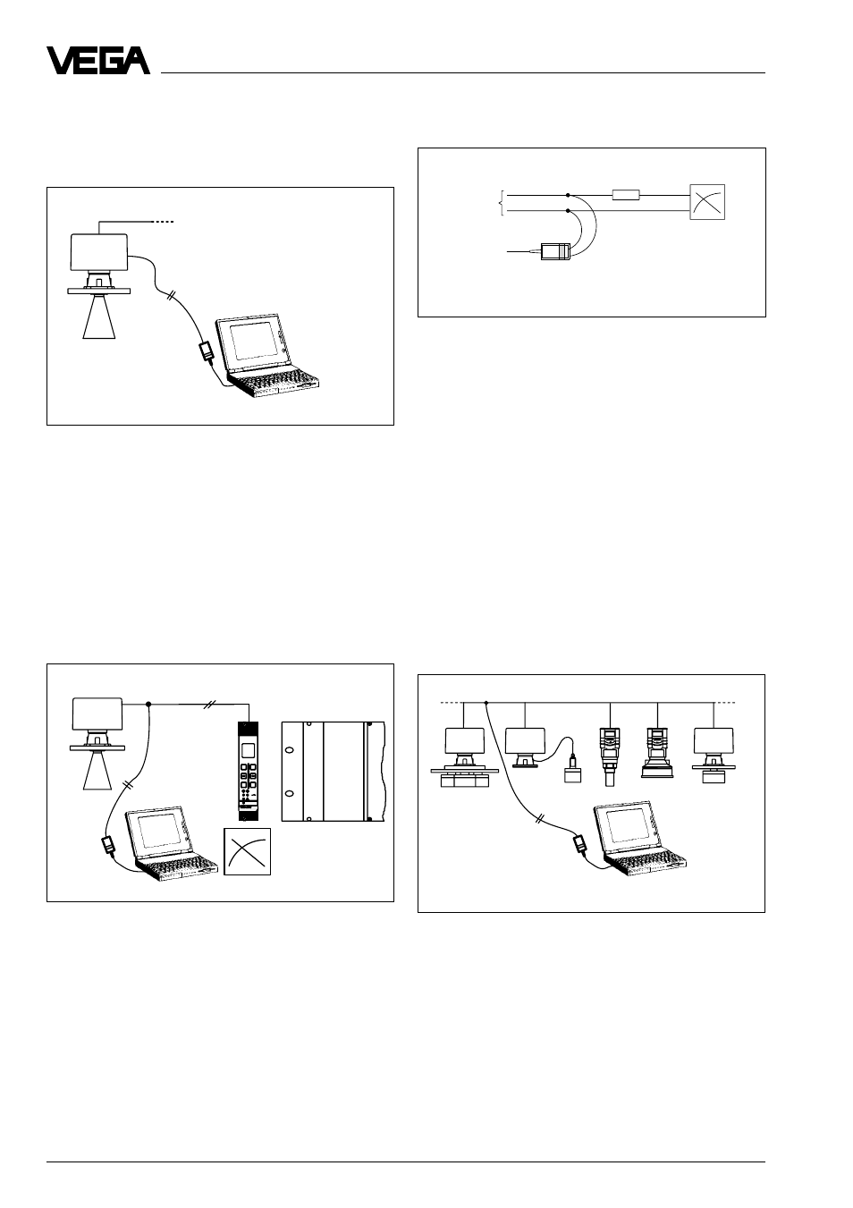
3.2 VVO on the 4 … 20 mA-line
Connection possibility via VEGACONNECT 2
on HART
®
-capable sensors on the
4 … 20 mA-line. It does not matter if the
power supply of the sensor is provided
separately or via the 4 … 20 mA-line.
A digital signal is additionally superimposed
to the 4 … 20 mA-output of the HART
®
-capa-
ble sensor. Note the inner resistor of the
connected processing. If this resistor is
<100
W (e.g. with an indicating instrument),
the digital signal will be damped. In this case
a load resistor of R = 100
W should be looped
into the 4 … 20 mA-line.
With analogue inputs of DCS-systems, this
resistor is in general >100
W, so that there will
be no damping.
3.3 VVO on the VBUS-line
ESC
OK
-
+
1
2
on
100
%
CONNECT
514 V
4 … 20 mA-line with superim-
posed HART
®
-signal
If several sensors are connected via one
BUS-line, VEGACONNECT 2 can be con-
nected to the BUS-line to adjust all other
sensors.