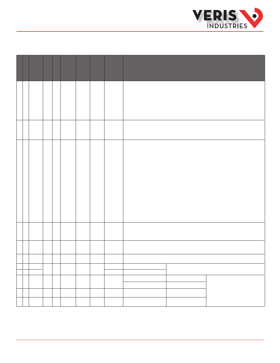
Modbus point map (cont.) – Veris Industries E50C3 Install User Manual
Page 23
ZL0103-0B
Page 23 of 26
©2013 Veris Industries USA 800.354.8556 or +1.503.598.4564 / [email protected] 10131
Alta Labs, Enercept, Enspector, Hawkeye, Trustat, Aerospond, Veris, and the Veris ‘V’ logo are trademarks or registered trademarks of Veris Industries, L.L.C. in the USA and/or other countries.
Other companies’ trademarks are hereby acknowledged to belong to their respective owners.
Installation Guide
Power Monitoring
E50B1, E50C2, E50C3
TM
E50C2 FDS
E50C3 L
og
E50xx REG.
R/W NV Format
Units
Scale
Range
Description
• 158
R/W NV UInt
0-10
Logging Read Page Register. Selects which of the Register Logs to read (see registers 169-178). 1-10 are valid
entries that put the meter into log reading mode, temporarily pausing logging. When set to 0 (no variable
selected for reading), normal logging resumes. The meter will buffer one set of log entries while in reading
mode if a sub-interval timeout occurs (read/write collision). Default is 0.
Warning: this buffered data will be written to the log and logging will resume on the following sub-interval
timeout whether the page register has been cleared or not, resulting in the appearance of data moving in the
buffer during reads. To avoid this, log buffer reads should be completed and this register set back to 0 in less
time than the Demand Sub-interval (preferred) or logging should be halted by setting Bit 1 in register 158
(logs may be missed)
• 159
R/W NV UInt
Logging Configuration Register (Bit Mapped):
Bit 0: Clear to 0 for Continuous log buffer mode. Set to 1 for Single Shot logging mode. Default is 0 (Continuous).
Bit 1: Clear to 0 to enable Logging. Set to 1 to halt logging. Default is 0 (Log).
• 160
R
NV UInt
Logging Status Register (Bit Mapped):
Bit 0: Log buffer full – Set to 1 when one single shot mode has filled the log buffer. The Logged Entry Count will
continue to increment. Cleared to 0 when logging is restarted (see reset command register 129).
Bit 1: Log Buffer Read Collision 1 – Set to 1 if the meter tried to save log data while the user was reading the
log (Logging Page Register has been set to something other than 0). On the first collision, the meter holds the
data until the next sub-interval and then writes the saved data to the log as well as the data for that interval.
This bit is cleared to 0 on the first demand interval with Logging Page Register = 0.
Bit 2: Log Buffer Read Collision 2 – Set to 1 on the 2nd attempt to save log data while the user is reading the log
(Logging Page Register is set to something other than 0). At this point the meter ignores the read condition
and does a double write, first of the values saved from the previous cycle, and then the present values. If
the read condition is not removed the meter continues to write the log data as it normally would. This bit is
cleared to 0 on the first demand interval with Logging Page Register = 0.
Bit 3: Logging Reset – The Log has been reset during the previous demand sub-interval.
Bit 4: Logging Interrupted – Logging has been interrupted (power cycled, log configuration change, etc.) during
the previous demand sub-interval.
Bit 5: RTC Changed – The Real Time Clock has been changed during the previous demand sub-interval.
Bit 6: RTC Reset – The Real Time Clock has been reset to the year 2000 and needs to be re-initialized.
• 161
R
NV UInt
0-32767
Log Buffer Wrap / Missed Log Counter. In continous mode, this counter increments each time the internal
circular log buffer wraps and overwrites old data. The total number of logged entries since the last log reset is:
(Register 161 x 5760) + Register 163. In single shot mode this counter is the number of log entries lost due to
the buffer being full. The counter is cleared on logging reset.
• 162
R
NV UInt
0-32767
Max Number of Logging Days. Based on the Sub-Interval Length and the depth of the log buffer, this register
shows the maximum number of days that data will be logged following a reset until the Buffer is full (Single
Shot Mode) or overwrites old data (Continuous).
• 163
R
NV UInt
0-32767
Number of Logged Entries since the log buffer wrapped or was reset. In single shot mode, this is the total
number of valid entries in the buffer. Any entries beyond this will read back as QNAN (0x8000).
• 164
R
NV ULong
kWh
E
0-0xFFFF
Real Energy Consumption (MSR)
Real Energy (Register 001/002) at the time of the most recent log entries.
• 165
0-0xFFFF
Real Energy Consumption (LSR)
• 166
R
NV UInt
Month /
Day
See Bytes
Most Significant Byte (MSB)
Least Significant Byte (LSB)
Date & Time of the newest entry in the log.
After a power cycle, resets to:
Day 01 Month 01
Hour 00 Year (20) 00
Day 1-31 (0x01-0x1F)
Month 1-12 (0x01-0x0C)
• 167
R
NV UInt
Year /
Hour
See Bytes
Hour 0-23 (0x00-0x17)
Year 0-199 (0x00-0xC7)
• 168
R
NV UInt
Minutes /
Seconds
See Bytes
Seconds 0-59 (0x00-0x3B)
Minutes 0-59 (0x00-0x3B)
Modbus Point Map (cont.)