Modbus point map (cont.) – Veris Industries E50C3 Install User Manual
Page 21
ZL0103-0B
Page 21 of 26
©2013 Veris Industries USA 800.354.8556 or +1.503.598.4564 / [email protected] 10131
Alta Labs, Enercept, Enspector, Hawkeye, Trustat, Aerospond, Veris, and the Veris ‘V’ logo are trademarks or registered trademarks of Veris Industries, L.L.C. in the USA and/or other countries.
Other companies’ trademarks are hereby acknowledged to belong to their respective owners.
Installation Guide
Power Monitoring
E50B1, E50C2, E50C3
TM
E50C2 FDS
E50C3 L
og
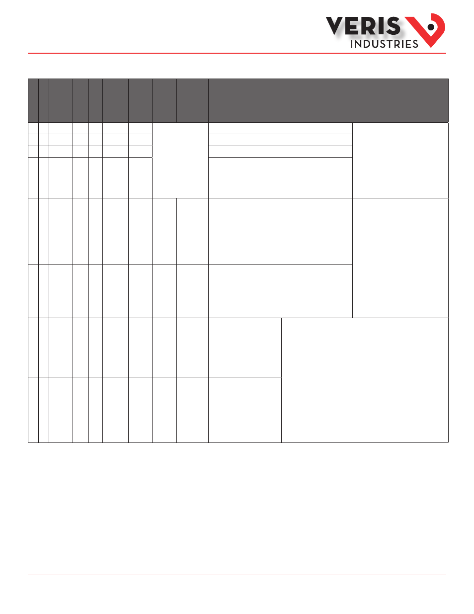
E50xx REG.
R/W NV Format
Units
Scale
Range
Description
•
• 138
R
SInt
-4 0.0001
-3 0.001
-2 0.01
-1 0.1
0 1.0
1 10.0
2 100.0
3 1000.0
4 10000.0
Scale Factor I (Current)
Scale Factors
Note: These registers contain a signed
integer, which scales the corresponding
integer registers. Floating point registers
are not scaled. Scaling is recalculated
when the meter configuration is changed.
•
• 139
R
SInt
Scale Factor V (Voltage)
•
• 140
R
SInt
Scale Factor W (Power)
•
• 141
R
SInt
Scale Factor E (Energy)
•
• 142
R/W NV UInt
%
1-99
Phase Loss Voltage Threshold in percent of system voltage (register
134). Default is 10 (%). Any phase (as configured in register 130)
that drops below this threshold triggers a Phase Loss alert - i.e.
if the System voltage is set to 480 V L-L, the L-N voltage for each
phase should be 277 V. When the threshold is set to 10%, if any
phase drops more than 10% below 277 V, (less than 249 V), or
if any L-L voltage drops more than 10% below 480 V (less than
432 V) the corresponding phase loss alarm bit in register 146 will
be true.
Phase Loss Output
Note: The phases tested are determined by
the System Type.
•
• 143
R/W NV UInt
%
1-99
Phase Loss Imbalance Threshold in Percent. Default is 25% phase
to phase difference. For a 3-phase Y (3 + N) system type (40 in
register 130), both Line to Neutral and Line to Line voltages are
tested. In a 3-phase Δ System type (31 in register 130), only Line
to Line voltages are examined. In a single split-phase (2 + N)
system type (12 in register 130), just the line to neutral voltage
are compared.
•
• 144
R/W NV UInt
Wh
10000,
1000,
100,
10
Wh (& VARh, if equipped with
FDS) Energy per Pulse Output
Contact Closure. If the meter
cannot find a pulse duration
that will keep up with the max.
system power (register 135), it
will reject the new value. Try a
larger value.
kWh Pulse Contacts
Note: The kWh pulse contact can keep up with a maximum power (Watts) of
1800000 x Wh pulse weight ÷ contact closure duration (in mses)
•
• 145
R
NV UInt
ms
500,
250,
100,
50,
25,
10
Pulse Contact Closure Duration
in msec. Read-only. Set to the
slowest duration that will keep
up with the theoretical max.
system power (register 135).
The open time ≥ the closure
time, so the max. pulse rate
(pulses per sec) is the inverse of
double the pulse time.
Modbus Point Map (cont.)