Data logging (e50c3 only, cont.), Standard modbus default settings, Read/write collision – Veris Industries E50C3 Install User Manual
Page 17
ZL0103-0B
Page 17 of 26
©2013 Veris Industries USA 800.354.8556 or +1.503.598.4564 / [email protected] 10131
Alta Labs, Enercept, Enspector, Hawkeye, Trustat, Aerospond, Veris, and the Veris ‘V’ logo are trademarks or registered trademarks of Veris Industries, L.L.C. in the USA and/or other countries.
Other companies’ trademarks are hereby acknowledged to belong to their respective owners.
Installation Guide
Power Monitoring
E50B1, E50C2, E50C3
TM
Data Logging
(E50C3 only,
cont.)
Read/Write Collision
If the demand sub-interval timeout occurs while the user is reading a page (register 158 ≠ 0), the log data will be held in RAM
until the next demand subinterval. At that time, both the saved data from the previous cycle and the new data will be written to
the log, whether the page register has been set back to 0 or not. Error bits in the Log Status Register (160) track these conditions.
Subsequent log writes will proceed normally. Provided the log read is concluded in less time than the demand sub-interval, this
mechanism handles the occasional collision and prevents the user from reading data as the buffer is being updated.
The Log Status Register has additional error flag bits that indicate whether logging has been reset or interrupted (power cycle,
etc.) during the previous demand sub-interval, and whether the Real-Time Clock has been changed (re-initialized to default date/
time due to a power-cycle or modified via Modbus commands).
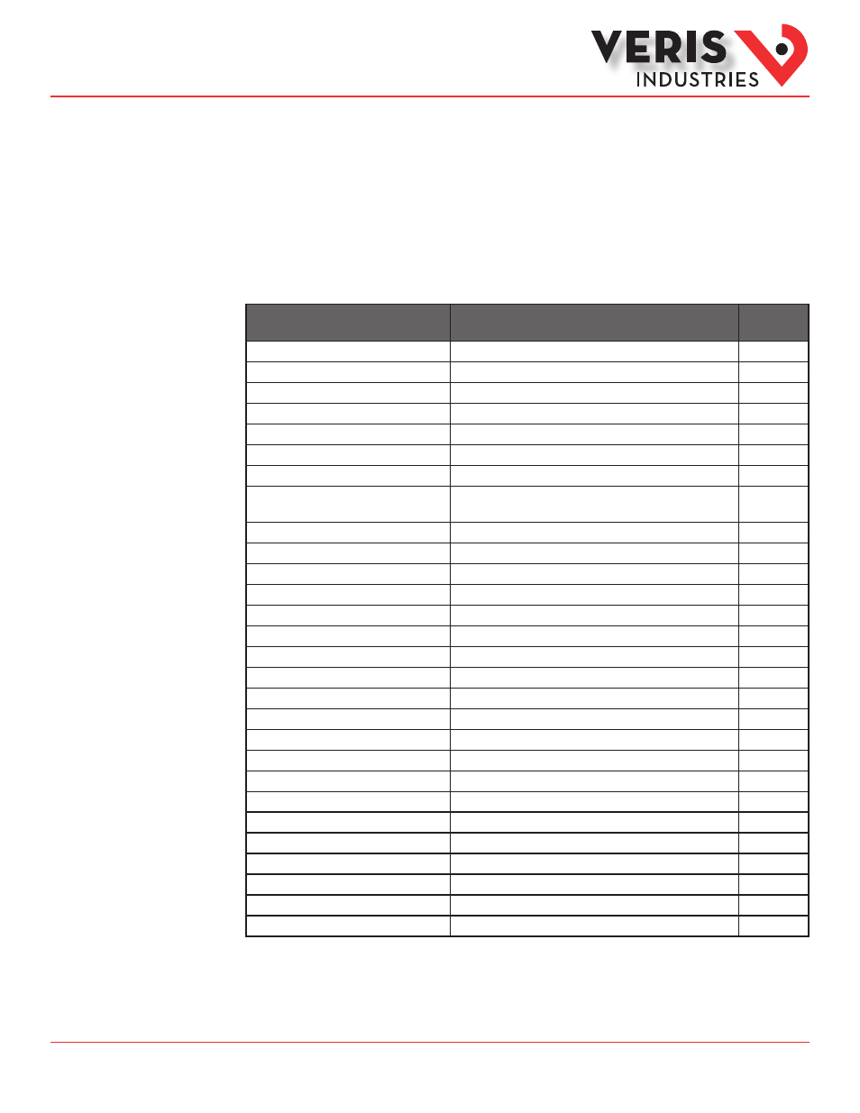
Setting
Value
Modbus
Register
Setup Password
00000
–
Reset Password
00000
–
System Type
40 (3 + N) Wye
130
CT Primary Ratio (if CTs are not included)
100A
131
CT Secondary Ratio
1V
132
PT Ratio
1:1 (none)
133
System Voltage
600 V L-L
134
Max. Theoretical Power
(Analog Output: full scale (20mA or 5V))
104 kW
135
Display Mode
1 (IEEE)
137
Phase Loss
10% of System Voltage (60V), 25% Phase to Phase Imbalance
142, 143
Pulse Energy
1 (kWh/pulse)
144
Demand: number of sub-intervals per interval
1 (block mode)
149
Demand: sub-interval length
900 sec (15 min)
150
Modbus Address
001
–
Modbus Baud Rate
19200 baud
–
Modbus Parity
None
–
Log Read Page
0
158
Logging Configuration Register
0
159
Log Register Pointer 1
1 (Real Energy MSR)
169
Log Register Pointer 2
2 (Real Energy LSR)
170
Log Register Pointer 3
29 (Reactive Energy MSR)
171
Log Register Pointer 4
30 (Reactive Energy LSR)
172
Log Register Pointer 5
37 (Real Demand)
173
Log Register Pointer 6
38 (Reactive Demand)
174
Log Register Pointer 7
39 (Apparent Demand)
175
Log Register Pointer 8
155 (Month/Day)
176
Log Register Pointer 9
156 (Year/Hour)
177
Log Register Pointer 10
157 (Minutes/Seconds)
178
Standard Modbus
Default Settings