Veris Industries Badger 3050 SERIES Install User Manual
Page 7
7
MODBUs points
All of these are available as Input Registers.
Addr Function
Flow 1 Rate (GPM)
1.
Flow 2 Rate
2.
Flow 1 Total (gallons)
3.
Flow 2 Total
4.
BTU Rate (kBTU/hr)
5.
BTU Total (kBTU)
6.
Batch 1 Count
7.
Batch 2 Count
8.
Temp 1 (deg F)
9.
Temp 2
10.
Temp Delta (T2-T1)
11.
UsB Port
Figure 12
RS485 Communication
Figure 13
Use
Standard Cable
USB Type A Male
To
Type Mini B 5 Pin Male
Connect to
Computer USB
Com Port
Model 3700
Model 345WT
or other
MODBUS
Master
Device
Shield
RS485 -
RS485 +
1 RS485 B
2 RS485 A
3 RS485 GND
4 LOOP +
5 LOOP -
6 GND
1 RS485 B
2 RS485 A
3 RS485 GND
4 LOOP +
5 LOOP -
6 GND
Figure 13
To communicate using the UsB Port requires
Windows Hyper-Terminal or other similar
communications software. This Port is part of
the analog Output Option card. see the UsB
Communications section of PROGRaMMING for
instructions on how to use this port.
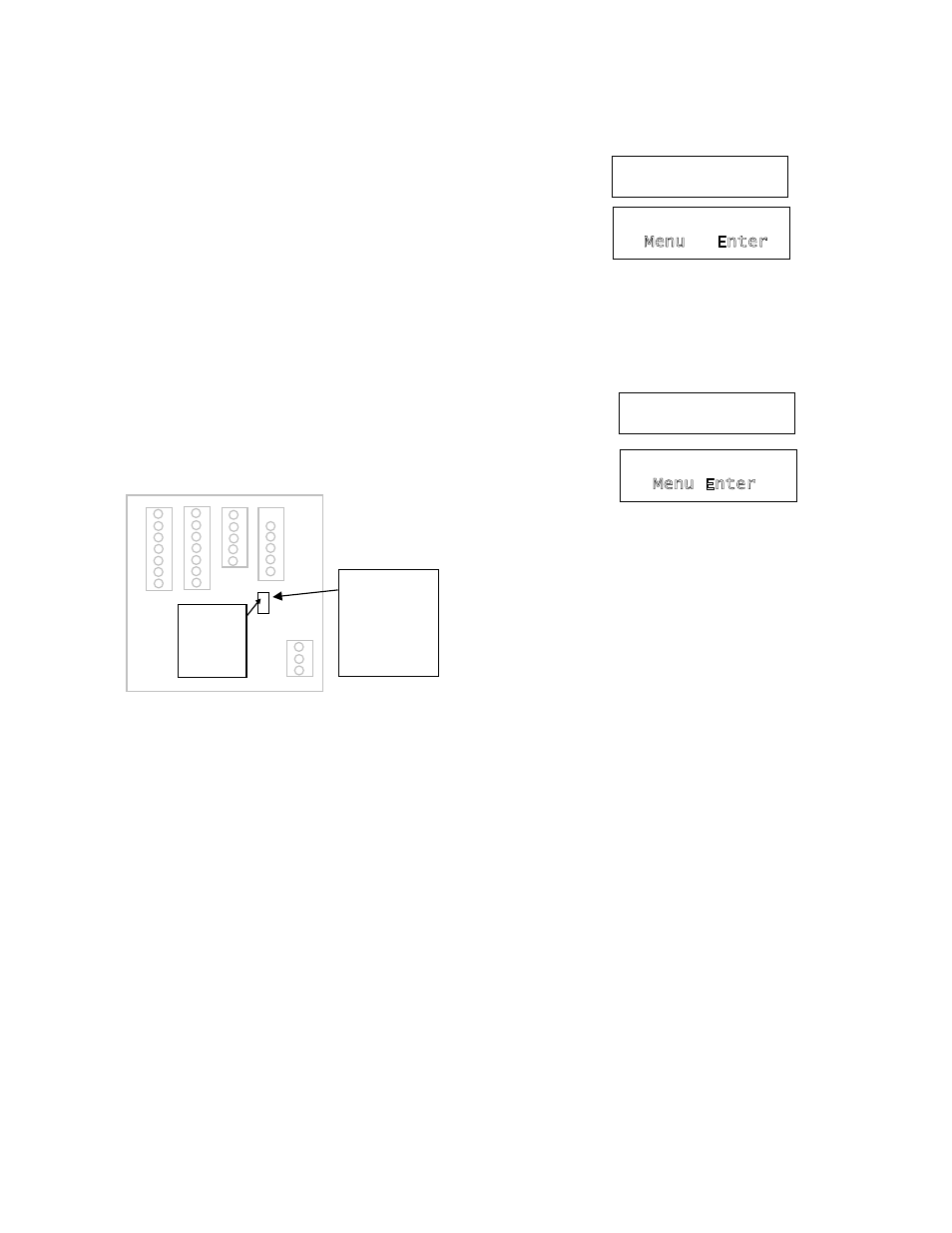
DIsPlaY aND KEY PaD
The Badger® Data Industrial® Model 3050 Monitor has
a two lines by sixteen character display with two modes
of operation, and Five (5) keys on the front panel for
programming. Two of the keys( Menu ;and Enter) serve a
single function while the three remaining keys (▲;▼; and
►) serve dual purposes.
When the Model 3050 is first powered up, it runs through
some internal self checks, while displaying “Badger Meter
DIC Initializing”, at the end of this cycle it’s normal display
will appear.
In the normal mode, if still using the factory default’s,
Flow Rate will be displayed on the top line, and Flow
Total displayed on the bottom. Both lines can be custom
defined in the field as desired. In the normal mode the
Enter key has no function.
Normal Mode Display
Normal Mode Display
Program Mode Display
0.0
GPM
0.0 gal
▲ ▼ ►
Menu Enter
RESET SETUP DIAG
▲ ▼ ►
Menu Enter
Program Mode Display
The other mode is the Programming Mode used to
configure the unit. Enter and exit this mode by pressing
the Menu key. See programming flow chart.
Normal Mode Display
Program Mode Display
0.0
GPM
0.0 gal
▲ ▼ ►
Menu Enter
RESET SETUP DIAG
▲ ▼ ►
Menu Enter
PROGRaMMING
With the normal display showing, pressing the Menu key
will enter the Programming Mode. In this mode, the three
arrow (▲▼►) keys are used in the Selection Screens
to select the option displayed above the key, Option List
Screens or used to scroll up or down a list of choices like
a pull down menu. It should be noted that most screens
presenting choices, show three choices, one for each
arrow button. When the number of choices exceeds
three, a small arrow ( → ) appears in the upper right side
of the display indicating there are more choices on that
level. Pressing the Enter key toggles to the next set of
choices. Once the selection has been made, the Enter
key also is used to complete the selection. Pressing the
Menu key returns back towards the normal screen.
selection screens
Most selection screens show three choices, one for each
arrow (▲▼►) button. When the number of choices
exceeds three, a small arrow ( → ) appears in the upper
right side of the display indicating there are more choices
on that level. Press the Enter key to view the next set
of choices. For example: pressing the Menu from the
normal screen shows the “ RESET SETUP DIAG” screen
Pressing the ▲key brings up the Reset Screens; the
▼key brings up the Setup Screens, and the ►key brings
up the Diagnostic Screens. If the ▼key is pressed the
screen would appear as follows: