Veris Industries Badger 3050 SERIES Install User Manual
Page 15
15
Page 19
USB Communication.
If the Model 3050 was ordered with an Analog Output Option Card, a Five Pin USB connector is also included.
As much as possible the commands mimic the use of the Front Panel controls.
To use this feature the following is required.
1. PC with USB ports, and Windows Hyper-terminal or other communications software
2. FTDI Virtual COM port Drivers
http://www.ftdichip.com/Drivers/CDM/Win2000/CDM_Setup.exe
3. USB 2.0 A to Mini-B 5 Pin cable
To communicate using Hyper-Terminal, use the following procedure.
1. Make sure that the Model 3050 has Mini-B 5 Pin connector on the back panel.
( The Model 3050 must have an Analog Output Option Card installed
and will be marked Model # 3xxx-1x )
2. Be sure that the appropriate FTDI Virtual COM port Drivers are installed on you computer.
3. Plug the USB 2.0 A end of the cable into an available USB port on your computer.
Plug the Mini-B 5 Pin end into the back of the Model 3050
4. Run Hyper-Terminal ( From the Windows Start Menu) and create a new connection, with a name and ICON.
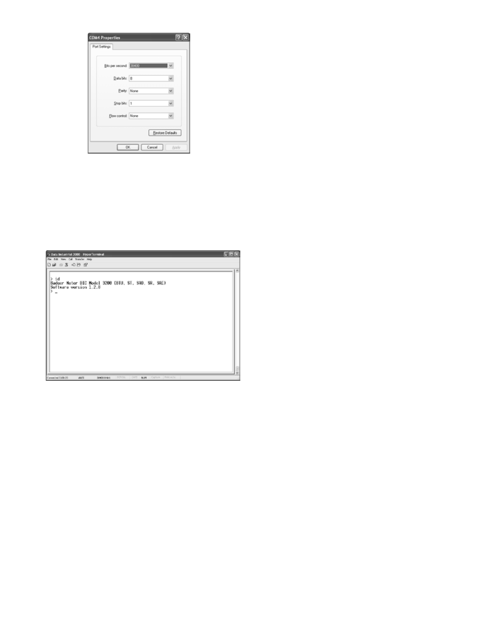
5. Configure this Port with 38400 baud, 8 data bits, 1 stop bit, no parity, and no flow control
When connected a “> “ symbol will appear in the
6.
upper left corner of the main HyperTerminal display
screen.Press the “Enter Key”. Both the Rx and Tx
LED’s on the front of the Series 3000 should flash
once, and the “Badger Meter DIC … Software
Version…” text message should appear.The Badger®
Data Industrial® Series 3000 is now communicating
ready to take commands from the list below.
Page 20
6. When connected a “
> “ symbol will appear in the upper left corner of the main HyperTerminal display screen.
Press the “Enter Key”. Both the Rx and Tx LED’s on the front of the Series 3000 should flash once, and
the “Badger Meter DIC … Software Version…” text message should appear.
The Series 3000 is now communicating ready to take commands from the list below.
USB COMMAND LIST
In the list below, brackets indicate an argument, specifying its type and value range.
For instance [0-18] stands for any number between 0 and 18 (inclusive).
Example:
“display line1 = 1” sets Line 1 of the display to display #1, which happens to be the totalizer for flow channel 1.
Diagnostics:
id -- show model number & software version
echo [on/off] -- turn on/off interactive command line:
with echo off, this interface is more amenable to scripting;
it still accepts the same commands.
Any command entered without an “ = “ sign and variable will display the current setting
Example: Typing “display line1” returns “0” which is the variable for Flow Rate
read flow [1-2] -- read the current flow on channel 1 or 2 in GPM
read flow [1-2] total -- read the current total flow on channel 1 or 2 in gallons
UsB COMMaND lIsT
In the list below, brackets indicate an argument,
specifying its type and value range. For instance [0-18]
stands for any number between 0 and 18 (inclusive).
Example:
“display line1 = 1” sets Line 1 of the display to display #1,
which happens to be the totalizer for flow channel 1.
Diagnostics:
id -- show model number & software version
echo [on/off] -- turn on/off interactive command
line:
with echo off, this interface is more amenable to
scripting;
it still accepts the same commands.
Any command entered without an “ = “ sign and variable
will display the current setting
Example: Typing “display line1” returns “0”
which is the variable for Flow Rate
read flow [1-2] -- read the current flow on channel 1 or 2
in GPM
read flow [1-2] total -- read the current total flow on
channel 1 or 2 in gallons
DIsPlaY CONFIGURaTION
display line1 = [0-18] -- set line 1 of the display
display line2 = [0-18] -- set line 2 of the display
valid options are:
0: flow 1 rate
1: flow 1 total
2: flow 2 rate
3: flow 2 total
4: flow 1+2 rate
5: flow 1+2 total
6: flow 1-2 rate
7: flow 1-2 total
8: flow 2-1 rate
9: flow 2-1 total
14: BTU rate
15: BTU total
16: temperature 1&2
17: temperature 1-2
display urate = [0.1-10] -- set the update rate of the
display, in seconds
FlOW INPUT CHaNNEl CONFIGURaTION
flow [1-2] sensor type = [0-4] -- flow sensor type:
0: PulseDI,
1: PulseKFactor,
2: PullupKFactor*
3: SineKFactor*
4: Analog*
flow [1-2] sensor dical k = [x] -- DI-type flow sensor k
flow [1-2] sensor dical off = [x] -- DI-type flow sensor
offset
flow [1-2] sensor kfact = [x] -- K factor for non-DI sensors
flow [1-2] sensor analog units = [0-19] -- flow units for
analog input
flow [1-2] sensor analog range = [0-4] -- current range for
analog input
flow [1-2] sensor analog high = [x] -- flow rate @max
current
flow [1-2] sensor analog low = [x] -- flow rate @min
current
flow [1-2] sensor avg = [0-100] -- averaging "time
constant", in seconds:
flow [1-2] rate units = [0-19] -- flow (channel) rate units to
display.
0: GPM
1: gal/s
2: gal/hr,
3: Mgal/day,
4: L/s,
5: LPM,
6: L/hr,
7: ft3/s,
8: ft3/min,
9: ft3/hr,