Veris Industries Badger 3050 SERIES Install User Manual
Page 6
6
Figure 8
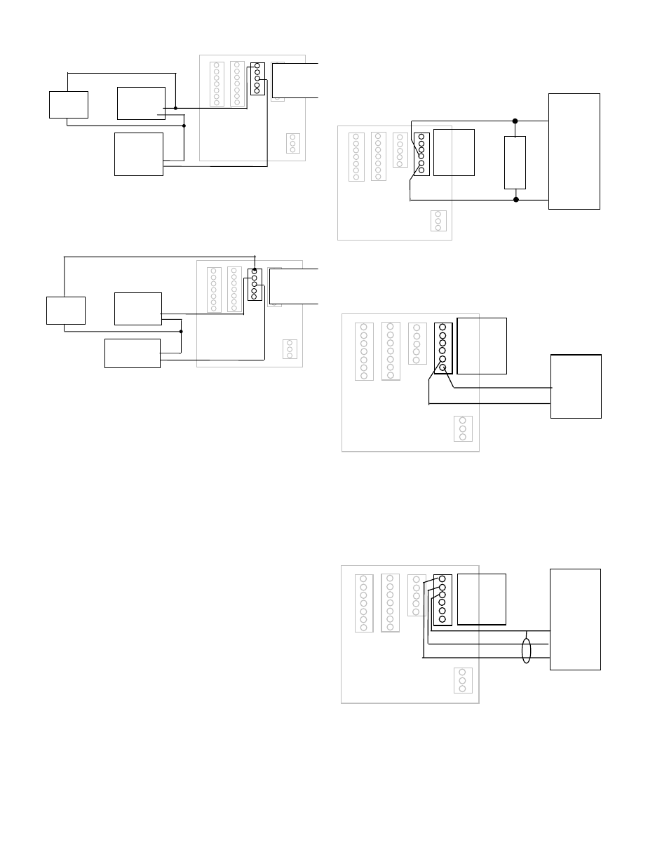
Relay and Switch Wiring Examples (continued)
( Chiller Control based on High Energy Usage with with indication
Figure 9
( Chiller Control based on Low Temperature Warning with indication
Chiller Motor
Starter
(1)
(2)
Power Supply
(Appropriate for
Motor Starter)
(COM)
(Line)
Indicator
Lamp
Chiller Relay
(1)
(2)
Chiller Controller
(COM)
(System Control Out)
Indicator
Lamp
1 RELAY 1 NO
2 RELAY 1 NC
3 RELAY 1 COM
4 PULSE 1 OUT
5 PULSE 2 OUT
1 RELAY 1 NO
2 RELAY 1 NC
3 RELAY 1 COM
4 PULSE 1 OUT
5 PULSE 2 OUT
Figure 8
Relay and switch Wiring Examples (continued)
Chiller Control based on High Energy Usage
with indication
Figure 8
Relay and Switch Wiring Examples (continued)
( Chiller Control based on High Energy Usage with with indication
Figure 9
( Chiller Control based on Low Temperature Warning with indication
Chiller Motor
Starter
(1)
(2)
Power Supply
(Appropriate for
Motor Starter)
(COM)
(Line)
Indicator
Lamp
Chiller Relay
(1)
(2)
Chiller Controller
(COM)
(System Control Out)
Indicator
Lamp
1 RELAY 1 NO
2 RELAY 1 NC
3 RELAY 1 COM
4 PULSE 1 OUT
5 PULSE 2 OUT
1 RELAY 1 NO
2 RELAY 1 NC
3 RELAY 1 COM
4 PULSE 1 OUT
5 PULSE 2 OUT
Figure 9
Chiller Control based on low Temperature Warning
with indication
OUTPUT OPTION CaRD:
If the Badger® Data Industrial® Model 3050 was ordered
with the Output Option card, it will have several additional
outputs.
These include the following.
Analog Output ( 0-20mA; or 4-20mA ) which can be
1.
converted externally to
0-5VDC, 1-5VDC with a 250 Ohm resistor; or,
0-10VDC or 2-10VDC with a 500 Ohm resistor.
A 15VDC Power Supply is provided to permit current
sinking or sourcing.
The Series 3050 has special software that permits
the Analog Output to be used as a PID Controller.
USB for direct access to a computer using a standard
2.
Mini-USB cable
RS-485 for fully addressable ModBus, or BACnet
3.
communication.
analog Output Wiring
Figure 10
Current Sourcing Analog Output
Figure 11
Current Sinking Analog Output
Analog Input
Device
12V Max@20mA
Analog -
Note:
Resistor only
required to convert
current to voltage
Like 0-5V
Not used for current
inputs like 4-20mA
Analog +
R
e
s
i
s
t
o
r
Analog Input
Device
Analog Input
+24VDC
1 RS485 B
2 RS485 A
3 RS485 GND
4 LOOP +
5 LOOP -
6 GND
1 RS485 B
2 RS485 A
3 RS485 GND
4 LOOP +
5 LOOP -
6 GND
Figure 10
Current sourcing analog Output
Figure 10
Current Sourcing Analog Output
Figure 11
Current Sinking Analog Output
Analog Input
Device
12V Max@20mA
Analog -
Note:
Resistor only
required to convert
current to voltage
Like 0-5V
Not used for current
inputs like 4-20mA
Analog +
R
e
s
i
s
t
o
r
Analog Input
Device
Analog Input
+24VDC
1 RS485 B
2 RS485 A
3 RS485 GND
4 LOOP +
5 LOOP -
6 GND
1 RS485 B
2 RS485 A
3 RS485 GND
4 LOOP +
5 LOOP -
6 GND
Figure 11
Current sinking analog Output
Rs485 Communication Wiring ( ModBus + BaCnet )
Figure 12
RS485 Communication
Figure 13
Use
Standard Cable
USB Type A Male
To
Type Mini B 5 Pin Male
Connect to
Computer USB
Com Port
Model 3700
Model 345WT
or other
MODBUS
Master
Device
Shield
RS485 -
RS485 +
1 RS485 B
2 RS485 A
3 RS485 GND
4 LOOP +
5 LOOP -
6 GND
1 RS485 B
2 RS485 A
3 RS485 GND
4 LOOP +
5 LOOP -
6 GND
Figure 12
Rs485 Communication