Veris Industries Badger 3050 SERIES Install User Manual
Page 5
5
for a wide variety of custom RTD’s and thermistors. Refer
to Programming Flow Charts. Contact the factory for
assistance for any custom inputs.
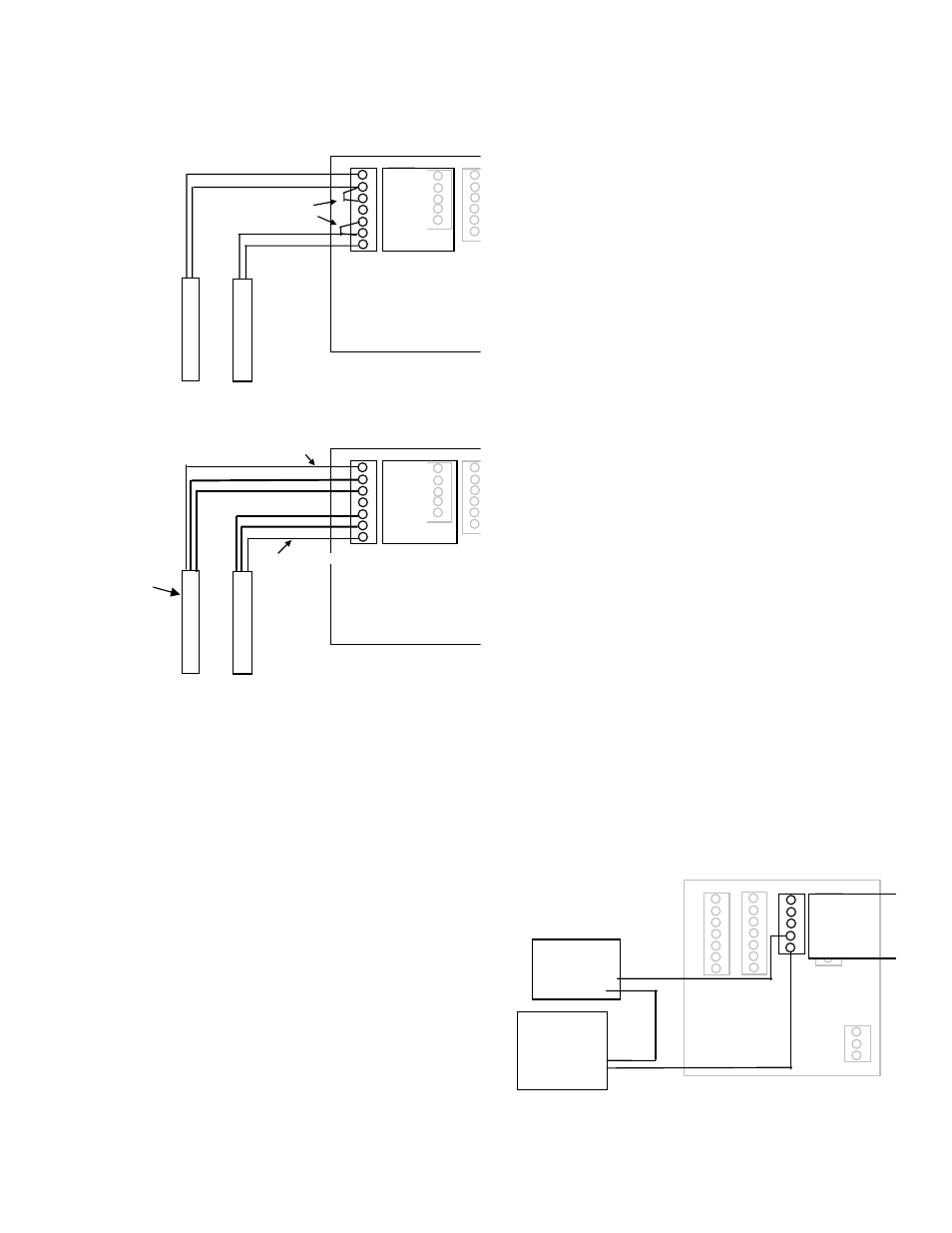
Wiring Two Wire Thermistors and RTD’s
Wiring Two Wire Thermistors and RTD’s
Wiring Three Wire RTD’s
1 TEMP 1 IN +
2 TEMP 1 IN -
3 TEMP 1 GND
4 SHIELD
5 TEMP 2 GND
6 TEMP 2 IN -
7 TEMP 2 IN +
Jumpers
2 Wire
Thermistor
Located
in same
Supply
or
Return line
Flow Sensor
2 Wire
Thermistor
3 Wire
RTD
T1
Located
in same
Supply
or
Return line
as
Flow Sensor
3 Wire
RTD
Same Colored 2 Wires
Different Color Wire
Different Wire
1 TEMP 1 IN +
2 TEMP 1 IN -
3 TEMP 1 GND
4 SHIELD
5 TEMP 2 GND
6 TEMP 2 IN -
7 TEMP 2 IN +
Wiring Three Wire RTD’s
Wiring Two Wire Thermistors and RTD’s
Wiring Three Wire RTD’s
1 TEMP 1 IN +
2 TEMP 1 IN -
3 TEMP 1 GND
4 SHIELD
5 TEMP 2 GND
6 TEMP 2 IN -
7 TEMP 2 IN +
Jumpers
2 Wire
Thermistor
Located
in same
Supply
or
Return line
Flow Sensor
2 Wire
Thermistor
3 Wire
RTD
T1
Located
in same
Supply
or
Return line
as
Flow Sensor
3 Wire
RTD
Same Colored 2 Wires
Different Color Wire
Different Wire
1 TEMP 1 IN +
2 TEMP 1 IN -
3 TEMP 1 GND
4 SHIELD
5 TEMP 2 GND
6 TEMP 2 IN -
7 TEMP 2 IN +
solid state switch and Form “C” Output Wiring
The Badger® Data Industrial® Series 3050 has one
Normally Open (N.O.) solid state switch, and one Solid
State Form “C” Relay. Check the specifications page
for maximum voltage and current ratings for each type
output.
These outputs are completely independent, electrically
isolated, and can be programmed as either Pulse, or Set-
point outputs.
When the function “Totalizer” is selected the unit of
measure and resolution are independent from the
displayed units, and can be programmed where 1 pulse
occurs once every 0000000.1 to 999999999.of units
selected, with any pulse width from 0001 to 9999mS.
When the “Alarm” is selected the unit of measure and
the resolution is independent from the displayed units,
it allows the unit to be programmed as either a High or
Low rate Set Point. Since the Set-point, Release Point,
and there associated time delays are fully independent
this output can be either a classical High Rate, or Low
Rate alarm depending on the settings selected. When
design-planning keep in mind that although both of these
outputs can be programmed as alarm points only the
Relay provides both N.O. and N.C. contacts. The switch
is a simple N.O. contact.
Examples:
High set-Point Control
The Set-Point “SETPT” must be a value greater than the
Release Point “RELP.”
The Relay output will have continuity between its “N.C”.
terminal and “COM” until the flow has exceeded the
Set-Point “SETPT” for a continuous period of time
exceeding the Set-Point-Delay “SDLY”, at which time
the N.C. connection with open, and the N.O. contact
will have continuity to the “COM” terminal. When the
flow has dropped below the Release Point “RELP” for a
continuous period of time exceeding the “RDLY” the relay
states will return to there original states. If the Latch has
been set to “ON” once the set-point and set-delay have
been satisfied the relay will not release until manually
reset. Sources for the Set-Point Control can be Flow
Rate, Energy Rate, T1, T2, or Delta T.
low set-Point Control
The Set-Point “SETPT” must be a value less than the
Release Point “RELP.”
The Relay output will have continuity between its
“N.C”. terminal and “COM” until the flow drops below
the Set-Point “SETPT” for a continuous period of time
exceeding the Set-Point-Delay “SDLY”, at which time
the N.C. connection with open, and the N.O. contact will
have continuity to the “COM” terminal. When the flow
has again risen above the Release Point “RELP” for a
continuous period of time exceeding the “RDLY” the relay
states will return to there original states. If the Latch has
been set to “ON” once the set point and set-delay have
been satisfied the relay will not release until manually
reset. Sources for the Set-Point Control can be Flow
Rate, Energy Rate, T1, T2, or Delta T.
Figure 7
Relay and Switch Wiring Examples
Mechanical
Counter
(+)
(-)
Power Supply
(Appropriate for
Counter ratings)
(-)
(+)
1 RELAY 1 NO
2 RELAY 1 NC
3 RELAY 1 COM
4 PULSE 1 OUT
5 PULSE 2 OUT
Figure 7
Relay and switch Wiring Examples