Veris Industries Badger 3050 SERIES Install User Manual
Page 14
14
UsB Communication
If the Badger® Data Industrial® Model 3050 was ordered
with an Analog Output Option Card, a five pin USB
connector is also included.
As much as possible the commands mimic the use of the
Front Panel controls.
To use this feature the following is required.
PC with USB ports, and Windows Hyper-terminal or
1.
other communications software
FTDI Virtual COM port Drivers http://www.ftdichip.
2.
com/Drivers/CDM/Win2000/CDM_Setup.exe
USB 2.0 A to Mini-B five pin cable
3.
To communicate using Hyper-Terminal, use the following
procedure.
Make sure that the Model 3050 has Mini-B five pin
1.
connector on the back panel. (The Model 3050 must
have an Analog Output Option Card installed and will
be marked Model # 3050-1x).
Be sure that the appropriate FTDI Virtual COM port
2.
Drivers are installed on you computer.
Plug the USB 2.0 A end of the cable into an available
3.
USB port on your computer.Plug the Mini-B five pin
end into the back of the Model 3050.
Page 18
Page 19
USB Communication.
If the Model 3050 was ordered with an Analog Output Option Card, a Five Pin USB connector is also included.
As much as possible the commands mimic the use of the Front Panel controls.
To use this feature the following is required.
1. PC with USB ports, and Windows Hyper-terminal or other communications software
2. FTDI Virtual COM port Drivers
http://www.ftdichip.com/Drivers/CDM/Win2000/CDM_Setup.exe
3. USB 2.0 A to Mini-B 5 Pin cable
To communicate using Hyper-Terminal, use the following procedure.
1. Make sure that the Model 3050 has Mini-B 5 Pin connector on the back panel.
( The Model 3050 must have an Analog Output Option Card installed
and will be marked Model # 3xxx-1x )
2. Be sure that the appropriate FTDI Virtual COM port Drivers are installed on you computer.
3. Plug the USB 2.0 A end of the cable into an available USB port on your computer.
Plug the Mini-B 5 Pin end into the back of the Model 3050
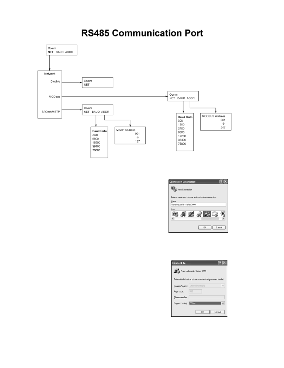
4. Run Hyper-Terminal ( From the Windows Start Menu) and create a new connection, with a name and ICON.
5. Configure this Port with 38400 baud, 8 data bits, 1 stop bit, no parity, and no flow control
Run Hyper-Terminal ( From the Windows Start Menu)
4.
and create a new connection, with a name and ICON.
Page 19
USB Communication.
If the Model 3050 was ordered with an Analog Output Option Card, a Five Pin USB connector is also included.
As much as possible the commands mimic the use of the Front Panel controls.
To use this feature the following is required.
1. PC with USB ports, and Windows Hyper-terminal or other communications software
2. FTDI Virtual COM port Drivers
http://www.ftdichip.com/Drivers/CDM/Win2000/CDM_Setup.exe
3. USB 2.0 A to Mini-B 5 Pin cable
To communicate using Hyper-Terminal, use the following procedure.
1. Make sure that the Model 3050 has Mini-B 5 Pin connector on the back panel.
( The Model 3050 must have an Analog Output Option Card installed
and will be marked Model # 3xxx-1x )
2. Be sure that the appropriate FTDI Virtual COM port Drivers are installed on you computer.
3. Plug the USB 2.0 A end of the cable into an available USB port on your computer.
Plug the Mini-B 5 Pin end into the back of the Model 3050
4. Run Hyper-Terminal ( From the Windows Start Menu) and create a new connection, with a name and ICON.
5. Configure this Port with 38400 baud, 8 data bits, 1 stop bit, no parity, and no flow control
Configure this Port with 38400 baud, 8 data bits, 1
5.
stop bit, no parity, and no flow control.