Veris Industries Badger 3050 SERIES Install User Manual
Page 4
4
Flow sensor Wiring
The Badger® Data Industrial® Series 3050 Flow Sensor
Inputs are extremely versatile, designed to accept either
two wire or three wire pulse inputs (Data Industrial 200
Series, SDI, or 4000 Series), zero crossing sine wave
inputs, or Analog inputs. Although different rear panel
terminals are used, all parameters are set with the LCD/
keypad interface. There are no internal or external
jumpers, switches, or potentiometers to move or adjust.
Four types of Pulse Input Types are accommodated.
Pulse-DI: Used for all Badger Data Industrial Flow
1.
Sensors.
Provides an internal Pull-Up resistor and uses “K”
and “Offset” values for calibration.
Pulse –K Factor:
2.
Accepts non Zero Crossing inputs but provides no
internal pull-up, classical “K” ( Pulses/Gal) values for
calibration.
Pullup-K Factor:
3.
Provides an internal Pull-Up resistor and uses
classical “K” ( Pulses/Gal) values for calibration.
Sine-K Factor:
4.
Accepts Zero Crossing low voltage sourcing devices,
with classical “K” ( Pulses/Gal) calibration.
all the above wire the same as shown in Figure 4.
see Programming Flow Chart for required input
configuration.
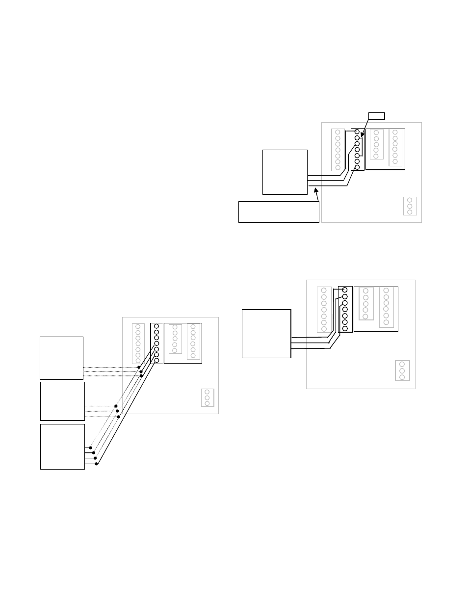
Figure 4
Data industrial Flow Sensor Wiring Examples
(Two and Three Wire Pulse Types)
Figure 5
4-20mA Analog Loop Powered Wiring
Figure 6
Voltage or Current Sourcing Analog Inputs
Two Wire
Flow Sensor
200 Series
Red
Black
Shield
Two Wire
Flow Sensor
SDI
3. Signal
2. Common
1. Shield
1 ANALOG IN+
2 ANALOG IN-
3 SHIELD
4 SENSOR IN
5 GND
6 SHIELD
7 SENSOR PWR
Three Wire
Flow Sensor
4000 Series
White
Black
Shield
Red
Two Wire
Analog Sensor
9.5V Max@20mA
Loop -
Shield
Loop +
Jumper
Note:
If sensor requires more than 9.5VDC at
20mA -Use a separate 24VDC supply.
Voltage or Current
Sourcing
Device
V+
V-
Shield
1 ANALOG IN+
2 ANALOG IN-
3 SHIELD
4 SENSOR IN
5 GND
6 SHIELD
7 SENSOR PWR
1 ANALOG IN+
2 ANALOG IN-
3 SHIELD
4 SENSOR IN
5 GND
6 SHIELD
7 SENSOR PWR
Figure 4
Data industrial Flow sensor Wiring Examples
(Two and Three Wire Pulse Types)
analog Input
As an alternative to the Pulse Inputs the Series 3050
can accept a Analog input. The input is non-isolated,
but can accept 0-1VDC ; 0-5VDC; 0-10VDC; 0-20mA;
and 4-20mA with both factory defined, and custom units
of measure. Low impedance 100 Ohm input for current
inputs optimizes performance and flexibility or loop
power supplies. Both the Low and High end scaling are
independent, and field configured by the installer.
see Programming Flow Chart for required input
configuration.
analog Flow sensor Input Wiring
Figure 4
Data industrial Flow Sensor Wiring Examples
(Two and Three Wire Pulse Types)
Figure 5
4-20mA Analog Loop Powered Wiring
Figure 6
Voltage or Current Sourcing Analog Inputs
Two Wire
Flow Sensor
200 Series
Red
Black
Shield
Two Wire
Flow Sensor
SDI
3. Signal
2. Common
1. Shield
1 ANALOG IN+
2 ANALOG IN-
3 SHIELD
4 SENSOR IN
5 GND
6 SHIELD
7 SENSOR PWR
Three Wire
Flow Sensor
4000 Series
White
Black
Shield
Red
Two Wire
Analog Sensor
9.5V Max@20mA
Loop -
Shield
Loop +
Jumper
Note:
If sensor requires more than 9.5VDC at
20mA -Use a separate 24VDC supply.
Voltage or Current
Sourcing
Device
V+
V-
Shield
1 ANALOG IN+
2 ANALOG IN-
3 SHIELD
4 SENSOR IN
5 GND
6 SHIELD
7 SENSOR PWR
1 ANALOG IN+
2 ANALOG IN-
3 SHIELD
4 SENSOR IN
5 GND
6 SHIELD
7 SENSOR PWR
Figure 5
4-20ma analog loop Powered Wiring
Figure 4
Data industrial Flow Sensor Wiring Examples
(Two and Three Wire Pulse Types)
Figure 5
4-20mA Analog Loop Powered Wiring
Figure 6
Voltage or Current Sourcing Analog Inputs
Two Wire
Flow Sensor
200 Series
Red
Black
Shield
Two Wire
Flow Sensor
SDI
3. Signal
2. Common
1. Shield
1 ANALOG IN+
2 ANALOG IN-
3 SHIELD
4 SENSOR IN
5 GND
6 SHIELD
7 SENSOR PWR
Three Wire
Flow Sensor
4000 Series
White
Black
Shield
Red
Two Wire
Analog Sensor
9.5V Max@20mA
Loop -
Shield
Loop +
Jumper
Note:
If sensor requires more than 9.5VDC at
20mA -Use a separate 24VDC supply.
Voltage or Current
Sourcing
Device
V+
V-
Shield
1 ANALOG IN+
2 ANALOG IN-
3 SHIELD
4 SENSOR IN
5 GND
6 SHIELD
7 SENSOR PWR
1 ANALOG IN+
2 ANALOG IN-
3 SHIELD
4 SENSOR IN
5 GND
6 SHIELD
7 SENSOR PWR
Figure 6
Voltage or Current sourcing analog Inputs
TEMPERaTURE INPUT:
The Badger
®
Data Industrial
®
Series 3050 can accept
inputs from either a pair of thermistors or RTD’s. The
inputs are labeled T1 and T2. Since the T1 sensor is
used to convert the volumetric flow (Example: GPM)
to the mass flow ( Example: Lbs/Hr) used in the Btu
Calculations, the sensor connected to T1 should be in the
same supply or return line as the Flow Sensor.
The temperature inputs of the 3050 are extremely
versatile. In addition to the factory default two wire10k
@77°F Type II Thermistors, and three wire 100 ohm
Platinum RTD’s, the unit can be programmed in the field