Installation guide, Configuration, Default dip switch settings – Veris Industries E31 Install User Manual
Page 9
Z205667-0E
PAGE 9
©2012 Veris Industries USA 800.354.8556 or +1.503.598.4564 / [email protected]
07121
Alta Labs, Enercept, Enspector, Hawkeye, Trustat, Veris, and the Veris ‘V’ logo are trademarks or registered trademarks of Veris Industries, L.L.C. in the USA and/or other countries.
TM
e31
INSTALLATIoN GUIDe
confIguratIon
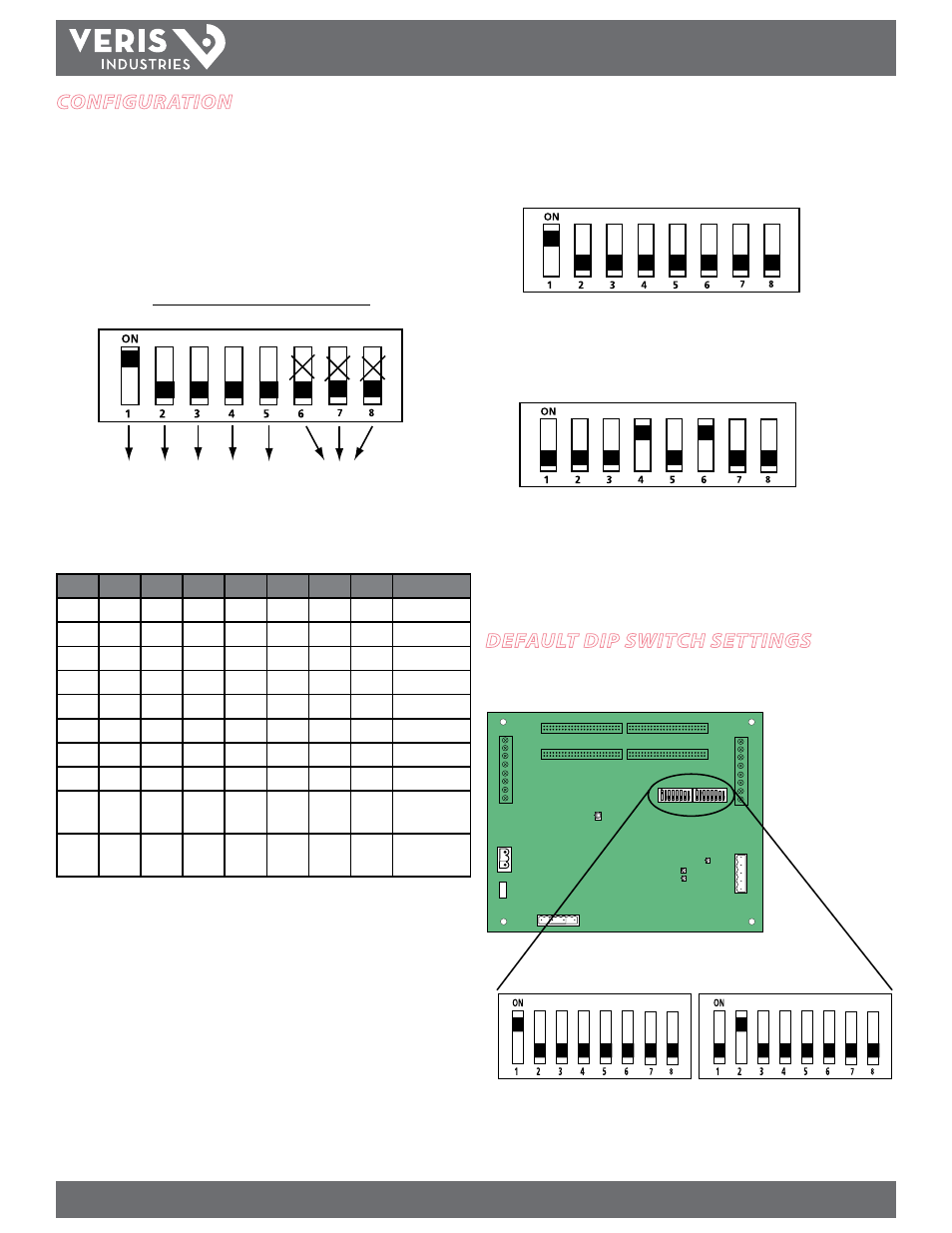
1. Communications Configuration: Communications parameters for the E31 series
are field selectable for your convenience. Please see the Product Diagram section
(page 2) for selector location. The following parameters are configurable:
• Baud Rate: 9600, 19200, 38400
• Parity On or Off
• Parity: odd or even
• Wiring: 2 or 4
Example: 2-wire 19200 Baud No Parity
B
ø
Reserved
B1 Off/
On
Parity
2/4
Wire
Odd/
Even
Parity
1
2
3
4
5
6
7
8
off
off
X
X
X
9600
on
off
X
X
X
19200
off
on
X
X
X
38400
on
on
X
X
X
Reserved
off
off
X
X
X
No Parity
on
off
X
X
X
Odd Parity
off
on
X
X
X
No Parity
on
on
X
X
X
Even Parity
on
X
X
X
4-wire RS-
485
off
X
X
X
2-wire RS-
485
2. Address Configuration: Each Modbus device on a single network must have
a unique address. Set the switch block to assign a unique address before the
device is connected to the Modbus RS-485 network. If an address is selected that
conflicts with another device, neither device will be able to communicate.
3. The E31 uses two logical addresses. Panel 1 uses the base address as set on the DIP
switches, and Panel 2 uses this base address + 1. Address the E31 as any whole
number between and including 1-246. Each unit is equipped with a set of 8 DIP
switches for addressing. See below.
1
LSB
MSB
1 2 4 8 16 32 64 128
DIP Switch Values
=
4. To determine an address, simply add the values of any switch that is on.
For example:
40
=
LSB
MSB
Switch number 4 has an ON Value of 8 and switch number 6 has an ON Value of 32.
(8 + 32 = 40). Therefore, the address for Panel 1 is 40, and the address for Panel 2 is
41.
See the Address Setup section (page 9) for a pictorial listing of the first 63 switch
positions.
default dIP sWItch settIngs
The E31 includes two DIP switches, as shown below. Switches are shown in their
default positions.
Comms Address
Comms Settings