Installation guide, Installation, Blink codes for status led – Veris Industries E31 Install User Manual
Page 4: Split-core ct accuracy
Z205667-0E
PAGE 4
©2012 Veris Industries USA 800.354.8556 or +1.503.598.4564 / [email protected]
07121
Alta Labs, Enercept, Enspector, Hawkeye, Trustat, Veris, and the Veris ‘V’ logo are trademarks or registered trademarks of Veris Industries, L.L.C. in the USA and/or other countries.
TM
e31
INSTALLATIoN GUIDe
InstallatIon
Observe precautions for handling static sensitive
devices to avoid damage to the circuitry that
is not covered under the factory warranty.
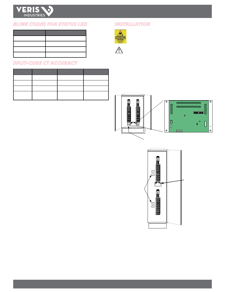
Disconnect power to the electrical panel and lock it out.
1. Install the acquisition board mounting bracket in the panel using screws and bolts
provided Panels can be oriented side-by-side (Figure 1A) or vertically (Figure
1B). A grounding connection is located on the mounting bracket, near the lower
right corner. Use this stud to ground the bracket when mounting on a non-
conductivesurface.
Figure 1A
Panel 1
Panel 2
Adapter boards
Figure 1B
Panel 1
Panel 2
Adapter boards
Main Circuit Board
blInk codes for status led
Color and Pattern
Status Description
Green, once per second
Normal operation
Amber, once per second
Volts or Amps clipping
Amber, twice per second
Invalid firmware image
Red, solid or blink
Diagnostic event detected
sPlIt-core ct accuracy
50A Split-Core CT
100A Split-Core CT 200A Split-Core CT
Voltage Rating 300VAC
600VAC
600VAC
Accuracy
±1%
±0.5%
±1%
Temperature
0° to 60°C
0° to 60°C
0° to 60°C
Agency
UL508 recognized,
EN61010
UL508 recognized,
EN61010
UL508 recognized,
EN61010