Installation guide, Operation, Quick install – Veris Industries E31 Install User Manual
Page 2: Dimensions, Circuit board and mounting bracket, Adapter board current sensors
Z205667-0E
PAGE 2
©2012 Veris Industries USA 800.354.8556 or +1.503.598.4564 / [email protected]
07121
Alta Labs, Enercept, Enspector, Hawkeye, Trustat, Veris, and the Veris ‘V’ logo are trademarks or registered trademarks of Veris Industries, L.L.C. in the USA and/or other countries.
TM
e31
INSTALLATIoN GUIDe
oPeratIon
The E31 Series Branch Current Monitor is designed to measure the current, voltage,
and energy consumption of up to 92 circuits (84 branch circuits, 2 3-phase mains, 2
neutrals) on a single board. One E31 can monitor up to two panels.
The E31 consists of a data acquisition board and up to 84 split-core current sensors
(50A, 100A, or 200A), with eight auxiliary inputs. Each conductor passes through a
current sensor and terminates at the breaker. Each sensor transmits the current data
to the data acquisition board.
Data is transmitted using an RS-485 Modbus protocol. Each data acquisition board
requires two addresses, one for each set of 42 current sensors and four auxiliary
inputs. Data is updated roughly every two seconds. As a circuit approaches the user-
defined threshold, the E31 activates the alarm indicators.
The E31A measures both current and power for the mains and branch circuits. The
E31B measures both current and power for the mains, and current only in each circuit.
The E31C measures current only for the mains and branch circuits.
quIck Install
Observe precautions for handling static sensitive
devices to avoid damage to the circuitry that
is not covered under the factory warranty.
1. Disconnect and lock out power. Use a properly rated voltage sensing device to
confirm power is off.
2. Mount the main acquisition board in the electrical enclosure.
3. Mount adapter boards to either DIN Rail or SNAPTRACK™.
4. Connect adapter boards to the main board via ribbon cable (sold separately).
5. Connect current transducers to the adapter boards.
6. Snap current sensors onto the conductors to be monitored. Note: ensure that
each split-core CT is closed and firmly seated.
7. Secure wires using strain relief cable ties.
8. Configure communication and addressing parameters using DIP switches.
9. Wire RS-485 communications.
10. Connect CTs to the auxiliary inputs and connect them onto the main conductors
in the enclosure (optional).
11. Wire control power and voltage taps (E31A and E31B only).
12. Download the free E3x configuration tool from www.veris.com to commission the
device for operation.
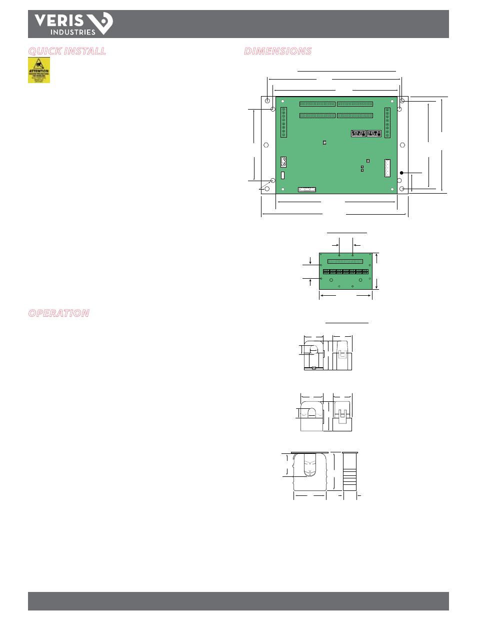
Circuit Board and Mounting Bracket
7.3”
(184 mm)
8.9”
(288 mm)
5.8”
(146 mm)
4.8”
(122 mm)
3.9”
(100 mm)
7.9”
(200 mm)
8.3”
(211 mm)
1.75”
(45 mm)
Ø = 0.2”
(5 mm)
Adapter Board
Current Sensors
dImensIons
4.6”
(117 mm)
2.75”
(70 mm)
1.00”
(26 mm)
1.00”
(26 mm)
D
E
C
B
A
D
E
B
A
C
50 Amp
A = 1.0” (26 mm)
B = 0.5” (11 mm)
C = 0.4” (10 mm)
D = 0.9” (23 mm)
E = 1.6” (40 mm)
100 Amp
A = 1.2” (29 mm)
B = 0.8” (20 mm)
C = 0.7” (16 mm)
D = 1.6” (40 mm)
E = 2.1” (53 mm)
200 Amp
A = 2.6” (66 mm)
B = 1.1” (28 mm)
C = 0.8” (19 mm)
D = 2.9” (74 mm)
E = 3.5” (90 mm)
A
B
C
E
D