Installation guide, Ab b, Data output – Veris Industries E31 Install User Manual
Page 3: Product diagram
Z205667-0E
PAGE 3
©2012 Veris Industries USA 800.354.8556 or +1.503.598.4564 / [email protected]
07121
Alta Labs, Enercept, Enspector, Hawkeye, Trustat, Veris, and the Veris ‘V’ logo are trademarks or registered trademarks of Veris Industries, L.L.C. in the USA and/or other countries.
TM
e31
INSTALLATIoN GUIDe
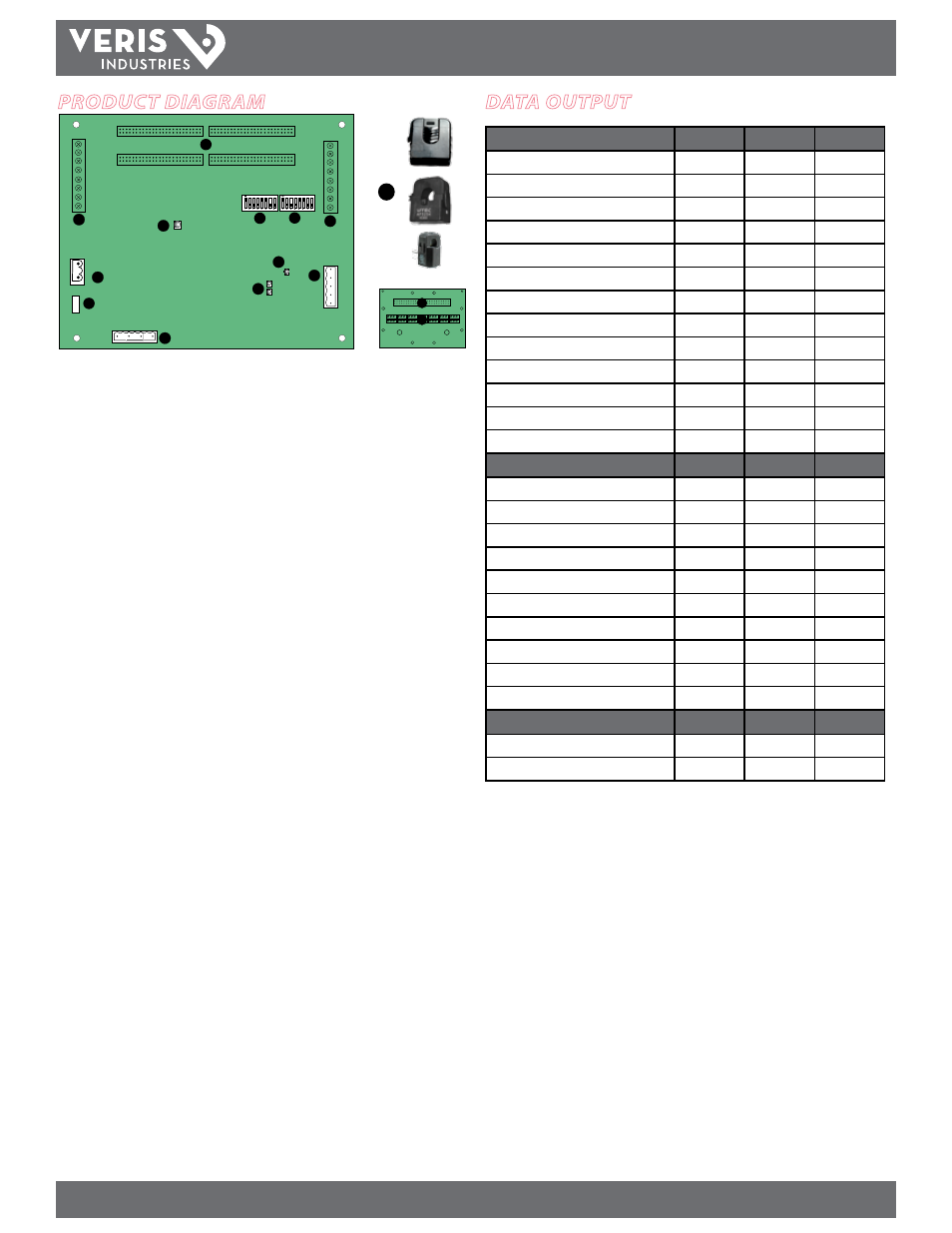
data outPut
Monitoring at Mains
E31A
E31B
E31C
Current per phase
Max. current per phase
Current demand per phase
Max. current demand per phase
Energy (kWh), total
Real Power (kW) per phase
Apparent Power (kVA)
Power factor, total *
Power factor, per phase
Voltage, L-L and average of 3 phases
Voltage, L-N and average of 3 phases
Voltage, L-N and per phase
Frequency (phase A)
Monitoring at Branch Circuit
Current
Max. current
Current demand
Max. current demand
Real power (kW)
Real power (kW) demand
Real power (kW) demand max.
Energy (kWh) per circuit
Power factor
Apparent Power (kVA)
Modbus Alarms
Voltage over/under
Current over/under
* Based on a 3-phase breaker rotation.
Product dIagram
7
1
2
3
4
5
6
2
8
9
10
A
A
B
B
11
1.
50-Pin Ribbon Cable Connectors:
Ribbon cables attach here for easy
connection of adapter boards to the data acquisition board. The two connectors
on the left are for panelboard 1; the two on the right are for panelboard 2.
Note: Connect Adapter Boards A and B to the correct ribbon cable connectors
for each panel. The top connector is for Adapter Board A, and the bottom
connector is for Adapter Board B.
Note: Ribbon Cable is not included with all E31 models. For ribbon cable
options, see Recommended Accessories on page 11.
2.
Auxiliary Inputs:
These 0.333VAC inputs are used for monitoring the main
breaker or other high amperage source. Inputs on the left are for panelboard 1;
inputs on the right are for panelboard 2.
3.
Control (Mains) Power Connection:
Easy 2-wire 90-277 VAC 50/60 Hz
connection.
4.
Control Power Fuse:
600VAC, 500mA time lag, factory-replaceable.
5.
Alive LED:
Red/green/amber LEDs. Blink codes are on page 3.
6.
Voltage Taps:
1, 2, or 3 phase plus neutral connections. For voltage sensing and
power calculations (no voltage taps on the E31C). Voltage taps are shared by both
panels.
7.
Communications Address DIP Switch:
Each Modbus device must have a unique
address. Switches are binary weighted. Left-most switch has a value of 1; right-
most switch has a value of 128. Note: switches set the address for panel 1; panel 2
is automatically set to (Panel 1 address + 1). See Configuration section for details.
8.
Communications Settings DIP Switch:
Configures baud rate, parity, 2- or
4-wire communications.
9.
RS-485 Connection:
Used for Modbus serial communications. The Universal plug
accomodates 2 or 4 wire connections.
10.
RS-485 LEDs:
The RX LED (closest to DIP switches) indicates the RS-485 is
receiving information; the TX LED indicates transmission of information.
11.
Power LED:
Indicates power to main board
12.
Branch Current Sensors:
Each split-core current sensor is capable of monitoring
conductors rated up to a maximum of 50, 100, or 200 amps. Up to 84 sensors can
be purchased with the E31 (see Recommended Accessories on page 10). One of
each style is pictured here.
13.
Ribbon Cable Connection
14.
CT Terminal Connections
12
13
14