Installation guide, A) (b) – Veris Industries E31 Install User Manual
Page 6
Z205667-0E
PAGE 6
©2012 Veris Industries USA 800.354.8556 or +1.503.598.4564 / [email protected]
07121
Alta Labs, Enercept, Enspector, Hawkeye, Trustat, Veris, and the Veris ‘V’ logo are trademarks or registered trademarks of Veris Industries, L.L.C. in the USA and/or other countries.
TM
e31
INSTALLATIoN GUIDe
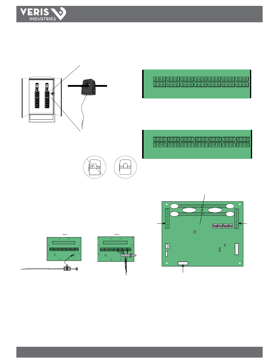
5. Install the current sensors onto the conductors to be monitored (Figure 5).
Sensors can be mounted facing either direction; orientation does not affect meter
accuracy. Note: Clean split-core contacts before closing. The hinge can detach,
allowing the base and the top to separate for easier cleaning and installation.
6. Plastic cable ties are included with the product for strain relief. Insert the strain
relief device into one of the available holes on the adapter board (Figure 6A).
Gather all current sensor wires connected to that adapter board and secure the
cable tie around them (Figure 6B).
(A)
(B)
Figure 6
Figure 5
✓
Close CTs until the clasp clicks
into place to ensure that contact
surfaces are firmly seated.
7. The adapter boards are silk screened with two rows of numbers. For applications
that require odd/even branch circuit numbering, use the row designated ODD or
EVEN. For applications that require sequential numbering, use the number row
marked SEQ (Figure 7).
Figure 7
41
39
37
35
33
31
29
27
25
23
21
19
17
15
13
11
9
7
5
3
1
1
2
3
4
5
6
7
8
9
10
11
12
13
14
15
16
17
18
19
20
21
ODD
SEQ
BLACK
WHITE
Adapter Board A numbering:
ODD
1 3 5 7 9 11 13 15 17 19 21 23 25 27 29 31 33 35 37 39 41
SEQ
21 20 19 18 17 16 15 14 13 12 11 10 9 8 7 6 5 4 3 2 1
42
40
38
36
34
32
30
28
26
24
22
20
18
16
14
12
10
8
6
4
2
42
41
40
39
38
37
36
35
34
33
32
31
30
29
28
27
26
24
24
23
22
EVEN
SEQ
BLACK
WHITE
Adapter Board B numbering:
EVEN
2 4 6 8 10 12 14 16 18 20 22 24 26 28 30 32 34 36 38 40 42
SEQ
22 23 24 25 26 27 28 29 30 31 32 33 34 35 36 37 38 39 40 41 42
Panel 1 uses base Modbus address as set by DIP switches.
Panel 2 uses base + 1 Modbus address as set by DIP switches.
Figure 8
Panel 2
Mains
Panel 1
Mains
Panel 2
Panel 1
A
B
Voltage taps are
shared by both panels
A
B
The 50 A CT accepts a maximum #2 AWG
(0.384” O.D.) wire with THHN insulation.
The 100A CT accepts a maximum 3/0 AWG
(0.584” O.D.) wire with THHN insulation.
The 200A CT accepts a maximum of 350 MCM
wire with THHN insulation.
Use this gauge wire or smaller for each circuit.