Installation guide – Veris Industries E31 Install User Manual
Page 5
Z205667-0E
PAGE 5
©2012 Veris Industries USA 800.354.8556 or +1.503.598.4564 / [email protected]
07121
Alta Labs, Enercept, Enspector, Hawkeye, Trustat, Veris, and the Veris ‘V’ logo are trademarks or registered trademarks of Veris Industries, L.L.C. in the USA and/or other countries.
TM
e31
INSTALLATIoN GUIDe
Panel 2
Panel 1
A
A
B
B
Note: Current sensor
orientation does NOT
affect meter accuracy.
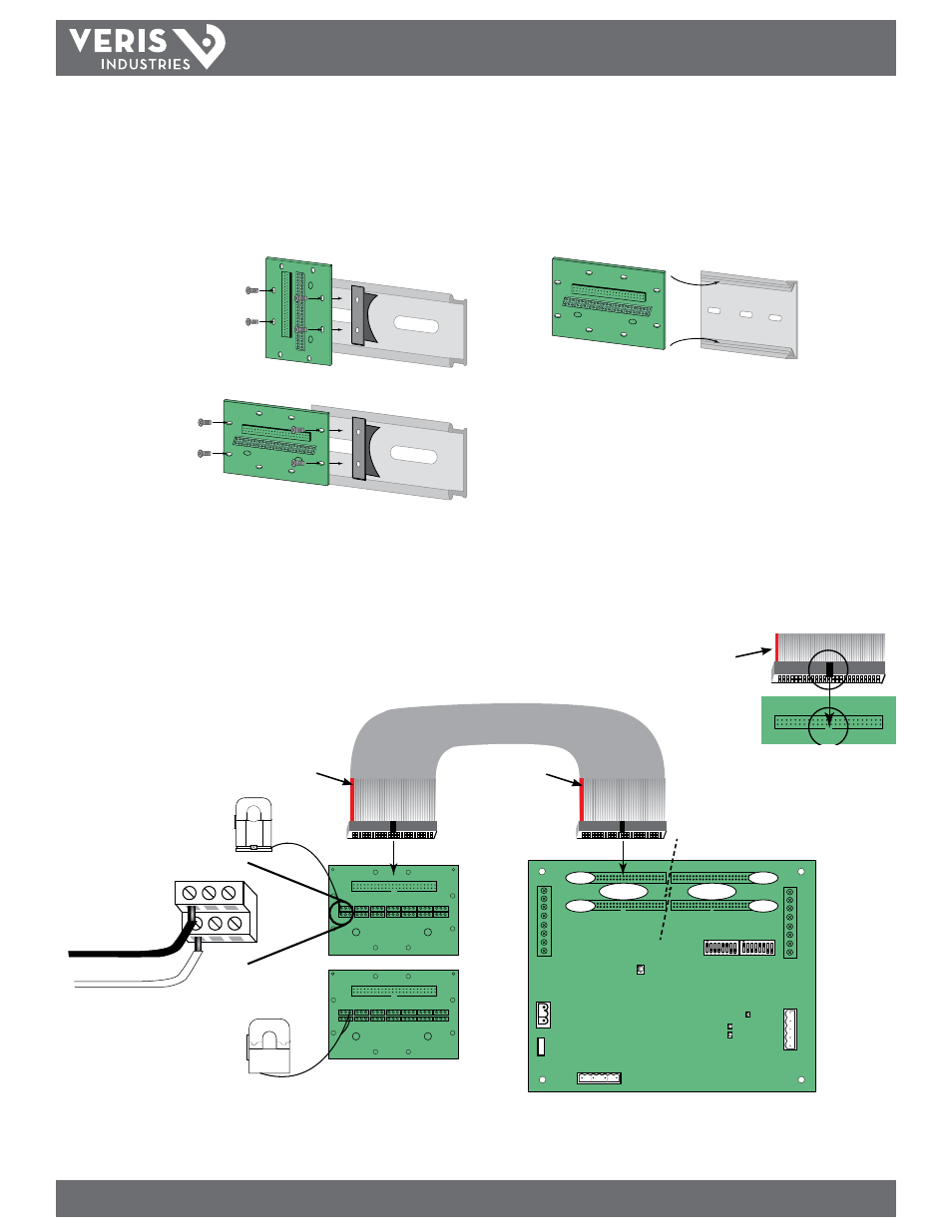
2. Mount the adapter boards to either DIN rail or SNAPTRACK.
A. DIN Rail: Use the supplied screws to secure the plastic DIN clip to the
adapter board. Affix the clip to the DIN rail (Figure 2).
B. SNAPTRACK: Secure the SNAPTRACK to the mounting surface. Click the
adapter board into place (Figure 3).
Figure 2
Figure 3
DIN Option 1: Vertical Mount
DIN Option 1: Horizontal Mount
3. Connect adapter boards to the main board using ribbon cable (Figure 4). Ribbon
cables are keyed to ensure proper installation. Orient cables so that the red
stripe is on the left.
Note: Flat and round ribbon cable are available from Veris. See
Recommended Accessories (page 10)
4. Connect current sensors to the terminals on the adapter boards (Figure 4).
Figure 4
Align ribbon cable key with
connector keyhole.
Orient ribbon cable so that
the red stripe is on the left
side of the connector.
Red Stripe
Red Stripe
Red Stripe