Technical data, Description – M&C TechGroup V..-H1 Series Operator's manual User Manual
Page 8
8
Gas sampling and gas conditioning technology
6-6.1-ME
7
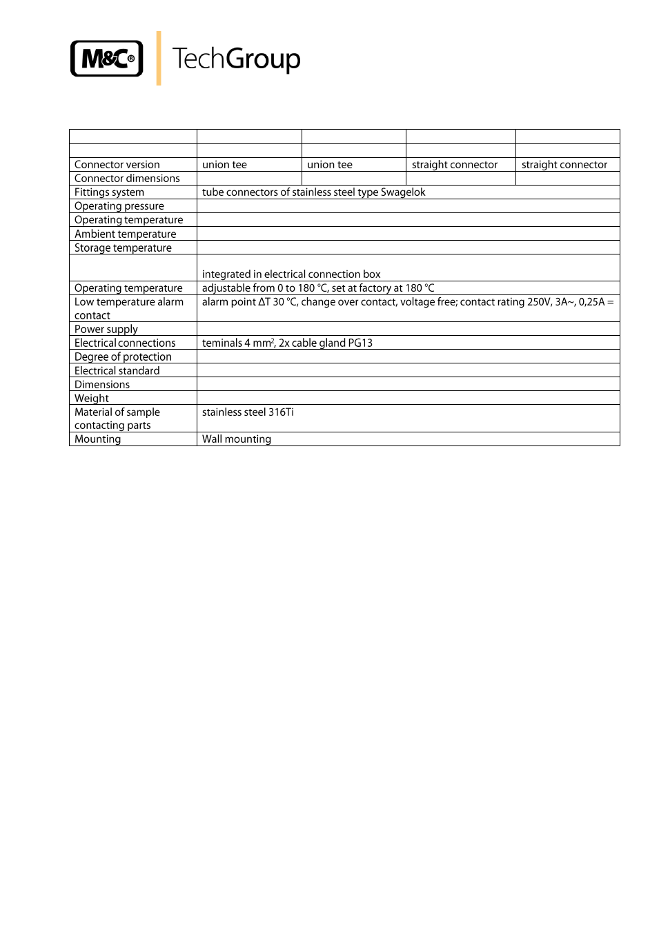
TECHNICAL DATA
T6-H1
T8-H1
V6-H1
V8-H1
Part number
10B1001 (a)**
10B1101 (a)**
10B1011 (a)**
10B1111 (a)**
3x ø 6 mm
3x ø 8 mm
2x ø 6 mm
2x ø 8 mm
max. 200 bar
max. +180 °C
-25 to +60 °C
-25 to +80 °C
Temperaturregler
capillary thermostat with high temperature limiter and low temperature alarm
230V 50Hz, 100VA **optionally 115V 60Hz (a)
IP 54 EN60529
EN 61010, EN60519-1
350 x 320 x 120 mm (w x h x d)
4,5 kg
8
DESCRIPTION
The M&C hose-/tube connectors T.-H1 and V.-H1 are fixed on a mounting plate, decoupled from heat
and covered with an insulated enclosure.
The heater consists of a heating element with high capacity. The temperature is adjustable on the
integrated thermostat up to 180 °C with high temperature limiter and low temperature alarm. The
connection box with integrated thermostat is installed outside the enclosure on the mounting plate.
The bushings for the heated sample lines in the enclosure are insulated with sockets of heat resistant
silicone. In order to avoid cold bridges, the connector is completely heated by means of a double-
ended thermal conducting jaw. For fixing the electrically heated sample lines type 3/4/5-N/M/H
– see
data sheet -2-6.1
–, mounting brackets are integrated.