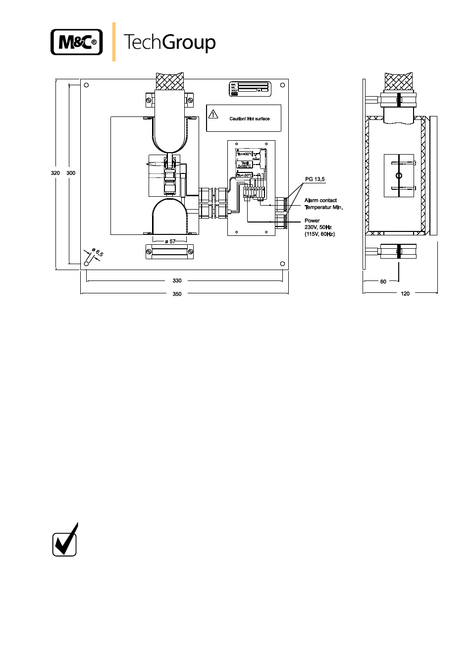
Mounting, Figure 2, Heated connector – M&C TechGroup V..-H1 Series Operator's manual User Manual
Page 10
10
Gas sampling and gas conditioning technology
6-6.1-ME
Figure 2
Heated connector
11
MOUNTING
For mounting the heated connector we recommend the following procedure:
Remove the lid of the heated connector by loosening the 4 screws;
Remove the thermal conductivity jaws by loosening the 2 screws M4;
Remove the upper part of the mounting clamp;
Put the heated sample line into the silicone cap and feed the end oft he tube through the hole
oft he cap;
Remove nut and compression rings of the fitting and put them in right order on the end of the
tube;
Put the end of the tube into the fitting;
The temperature-resistant, stainless steel connectors supplied by M&C have a double ferrule
system to ensure reliable sealing. After tightening the nuts of these connectors by hand, they
should then be tightened exactly 1¼ of a turn using a flat spanner and are then properly
mounted;
H I N W E I S !
If a PTFE tube is used as sample line, an insert must under all
circumstances be inserted in the end of the tube in order to prevent the
tube being pressed together.
Make sure that the connection is leak proof!
Retrofit the upper part of the mounting clamp;
After connection of the heated sample lines retrofit the thermal conductivity jaws and the lid;