Electrical installation, Figure 5, Electrical connections – M&C TechGroup N9 KP18 Operator's manual User Manual
Page 12
12
Gas sampling and conditioning technology
6-1.2.1ME
10.2
ELECTRICAL INSTALLATION
When making the electrical installation the safety regulations must be observed. In particular make
sure that the electricity supply is isolated before trying to connect the pump..
W A R N I N G !
When connecting the equipment, please ensure that the supply
voltage is identical with the information provided on the model
type plate.
The supply voltage is only allowed to deviate max. +6 % - 10% from
the indication on the model type plate.
N O T E !
Attention must be paid to the requirements of IEC 364 (DIN VDE
0100) when setting high-power electrical units with nominal volt-
ages of up to 1000 V, together with the associated standards and
stipulations.
The main circuit of the pump type KPE must be equipped with a
fuse corresponding to the nominal current (over current protec-
tion); (EN 60335-1)
The main circuit of the pump type KP18 is equipped with a fuse
corresponding to the nominal current (over current protection);
(EN 60335-1)
For electrical details see technical data.
The earth wire (ground) must be connected to the motor.
The pump must be installed so that contact with live parts (connections, possibly windings) is
impossible.
We recommend that a fuse is installed in the motor supply circuit; the operating current is given in
the technical data
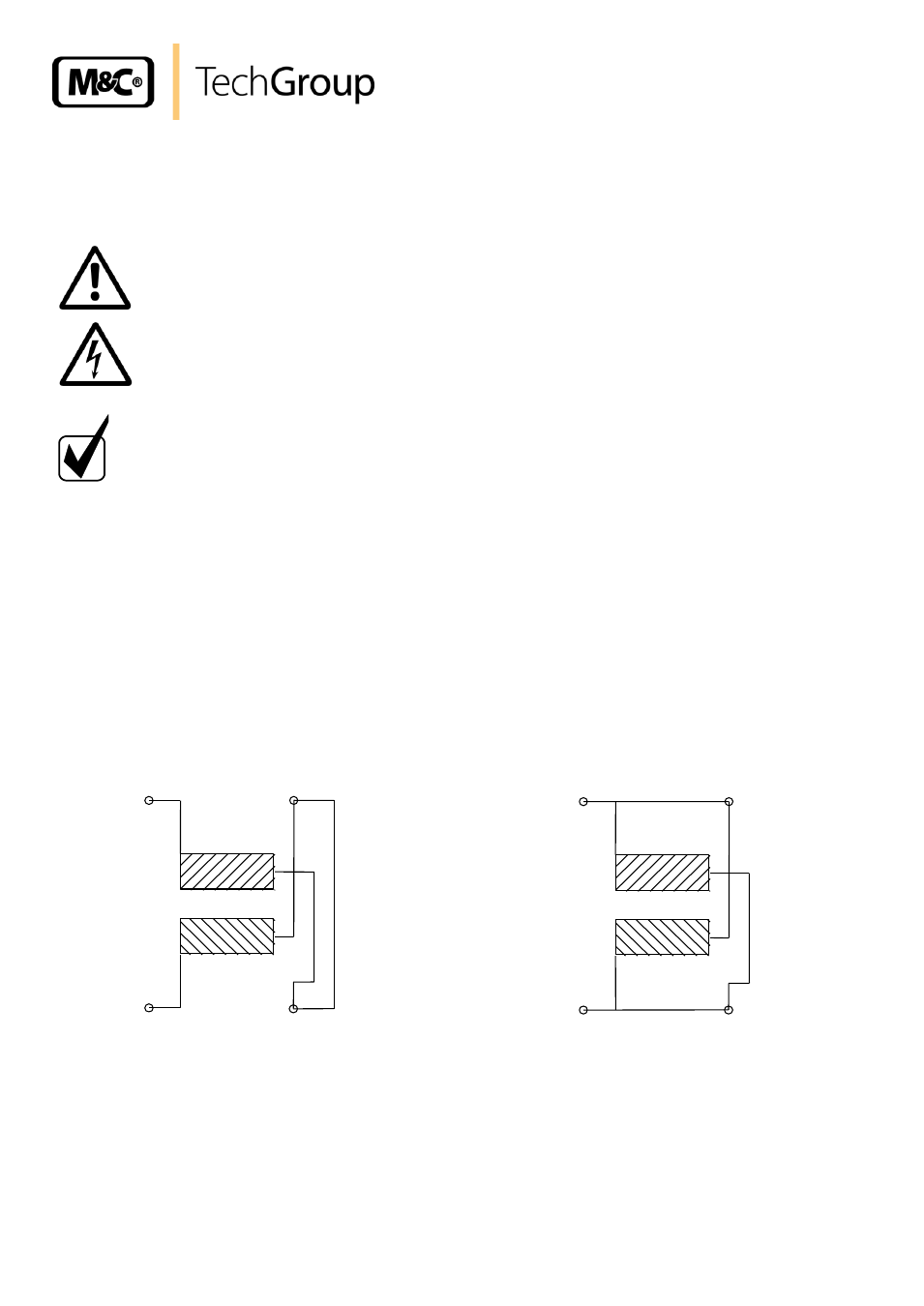
Mains 230V
N
L
wt
b/wt
rd
bl
Connection
Mains 115V
N
L
wt
b/wt
rd
bl
Connection
Bridge
Figure 5
Electrical connections