Preparation for installation, Mounting – M&C TechGroup SP10 Operator's manual User Manual
Page 10
10
Gas sampling and gas conditioning technology
2-0.1.1-ME
12
PREPARATION FOR INSTALLATION
Please pay attention to the following points:
Select the optimal sampling point in accordance with the generally applicable guidelines or consult
the competent persons.
Locate the sampling point in such a way that there is adequate space for inserting and removing
the gas sample probe and pay attention to the insertion length of the probe tube.
Make certain that the gas sample probe is easily accessible so that you can carry out any subse-
quent maintenance work without trouble.
Design and isolate the bleeder connection in such a way that the temperature of the whole connec-
tion is always above the acid dew point in order to avoid corrosion and blockage problems.
If the ambient temperature in the area of the bleeder connection is >80
C as a result of radiated
heat, then a radiated heat deflector must be mounted to protect the probe.
The mounting flange at the bleeder connection should comply with DN65 PN6. If other connection
sizes are required, a special adapter flange can be supplied as an option (Part No. 20S9004) .
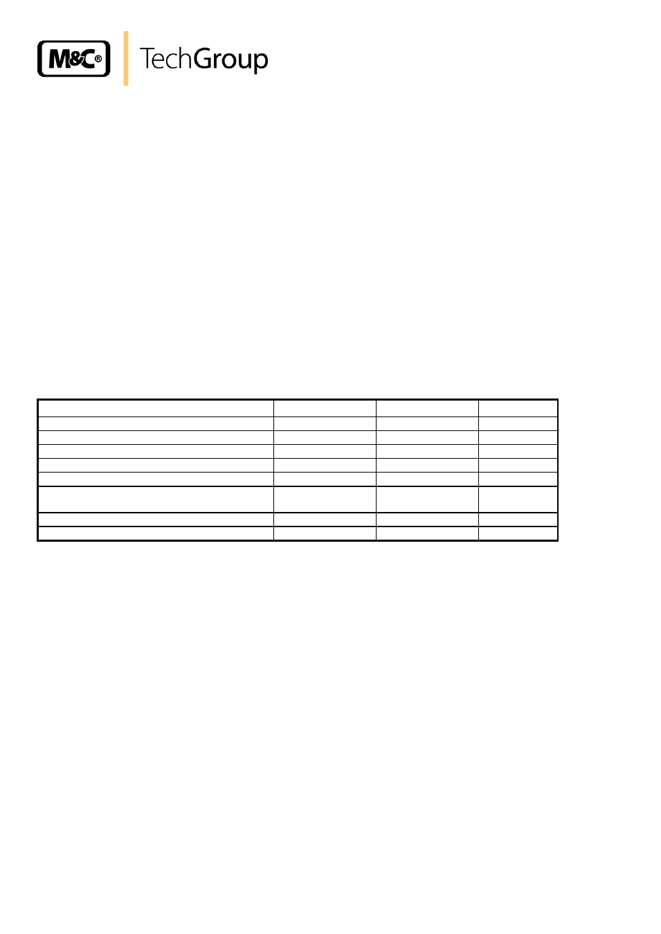
Before mounting, the gas sample probe must be adjusted to the existing operating conditions. We
recommend to check the existing parameters accordingly to the following table:
Weatherproof mounting position
_____present
_____install
Low/overpressure situation
mbar
bar
Process temperature
°C, Min.
°C, Max.
Dust loading
g/m³
Dust composition - grain size
µm
Gas composition
corrosive
toxic
explosive
Parameters to be measured, e.g. 02, CO,
SO2, NOX, ...,
Vol.%
mg/Nm³
ppm
Required gas flow
l/rh, Min.
l/hr, Max.
Required reaction time T90
sec.
13
MOUNTING
M&C SP10 resp. SP10-H gas sample probes are designed for stationary use and if properly selected
and mounted a long service life and maintenance are guaranteed.
It is advisable to mount the gas sample probe in a position which has a 10
inclination to the process
(not necessary for the function of the probe ).
Screw the prefilter directly on to the 1” outer thread with the 1” flat gasket and tighten.
If an extension tube is used, it should be mounted between the gas sample probe and the pre-filter.
If the gas sample probe connection does not correspond to the standard flange connection DN65
PN6, then the optionally supplied adapter flange should be mounted to the probe.
Before fixing the gas sample probe at the bleeder connection first attach the flange gasket to the
mounting flange.
The temperature-resistant, stainless steel connectors supplied by M&C have a double-blade ring sys-
tem to ensure reliable sealing. After tightening the nuts of these connectors by hand, they should then
be tightened exactly 1 1/4 of a turn using a flat spanner and are then properly mounted.