Wiring for dual inverter configurations, Installing the isc-s cable, Ac neutral wiring for dual configurations – Xantrex Technology ACCB User Manual
Page 51: Wiring for dual inverter configurations –39
Wiring for Dual Inverter Configurations
975-0046-01-01
1–39
Wiring for Dual Inverter Configurations
Series stacked
Sine Wave Plus
inverters with
ACCB
s installed are wired
essentially the same as single inverters, with the following differences.
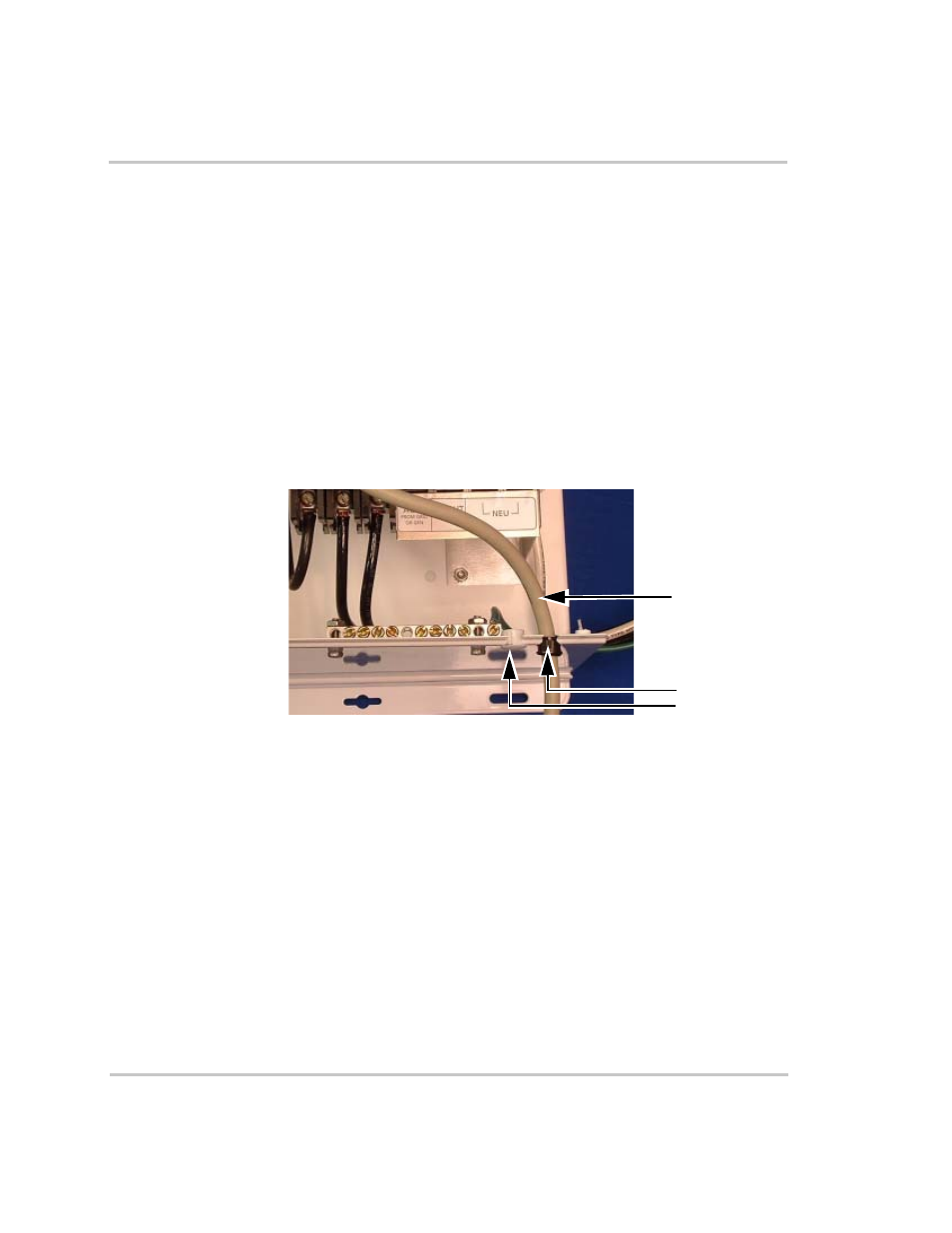
Installing the ISC-S Cable
The ISC-S cable must be run through one of the ISC-S/ICM cable slots
provided on the sides of the
ACCB
(see
). The
cable slots are blocked with hole plugs. These hole plugs must be
removed before inserting the ISC-S cable.
Remove the hole plug for the slot to be used by the cable only. Do not
remove any other hole plugs. Ensure that the all the other hole plugs are
still in place as shown in
AC Neutral Wiring for Dual Configurations
All of the AC wiring for dual
Sine Wave Plus
inverters remains the same,
except for two changes in the neutral wiring:
1. All NEUTRAL IN wiring goes only to the neutral terminals in the L1
ACCB
(attached to the L1
Sine Wave Plus
inverter).
2. A neutral bond between the inverters is created by connecting an
owner supplied #6 AWG THHN neutral wire (white) from the
ACCB
neutral terminal attached to the L1
Sine Wave Plus
inverter to the
ACCB
neutral terminal attached to the L2
Sine Wave Plus
inverter.
This wire should be long enough to pass from the L2 inverter AC
terminal block, through adjacent knockouts on both
ACCB
s, to the
L1 inverter
ACCB
terminal block.
Figure 1-34 ISC-S Cable in an ISC-S/ICM Cable Slot of the
ACCB
ISC-S Cable
Grommet
Hole Plug