Module set up -3, Circuit module set up -3, Control module setup -3 – Western Telematic AFS-16-1 User Manual
Page 21: The a/c/b connectors -3, Circuit module jumper -3
4-3
Hardware Installation
E
D
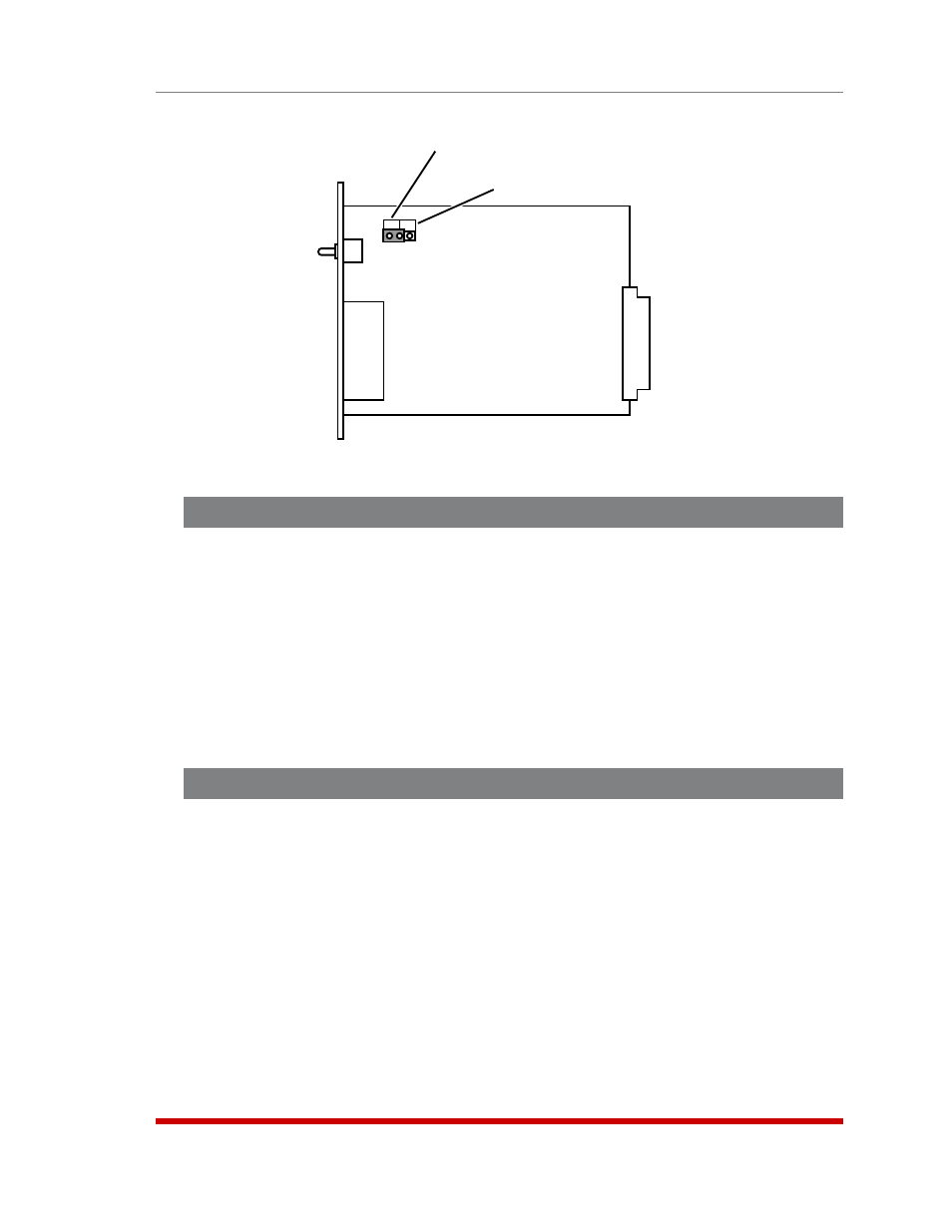
Enable
Disable
Figure 4.3: Circuit Module Jumper
4.5. Module Set Up
4.5.1. Circuit Module Set Up
The A/B Switch Jumper on the Circuit Module card (Figure 4.3) enables/disables the
individual Circuit Module’s A/B Switch. If you wish to disable manual A/B switching
control at a specific Module, then the A/B Switch Jumper on that Module must be set in
the "Disable" position.
4.5.2. Control Module SetUp
The Control Module includes a jumper that can be used to configure the AUX Connector
for use with the Monitor/Alarm Input feature. If you intend to use the Input Monitor
Alarm, then this jumper should be set as described in Section 7.6.
4.6. The A/C/B Connectors
Each AFS-16 Circuit Module includes three RJ45 connectors: a "C" (Common)
connector, an "A" (Primary Fallback) connector and a "B" (Secondary Fallback)
connector. Use an RJ45 Ethernet cable to connect devices to the A/C/B ports as
required.
This completes the AFS-16 installation instructions. Please proceed to the next Section
for instructions regarding basic unit configuration.