3 memory module - 5 – Toshiba B-570 SERIES User Manual
Page 83
3-6
EM18-33010A
3. INSTALLATION PROCEDURE FOR THE OPTIONAL EQUIPMENT
Max. drawing size (on-the-fly)
(W)x(H) (mm)
138.0 x 149.3
138.0 x 234.6
138.0 x 320.0
138.0 x 405.3
138.0 x 490.7
138.0 x 576.0
138.0 x 661.3
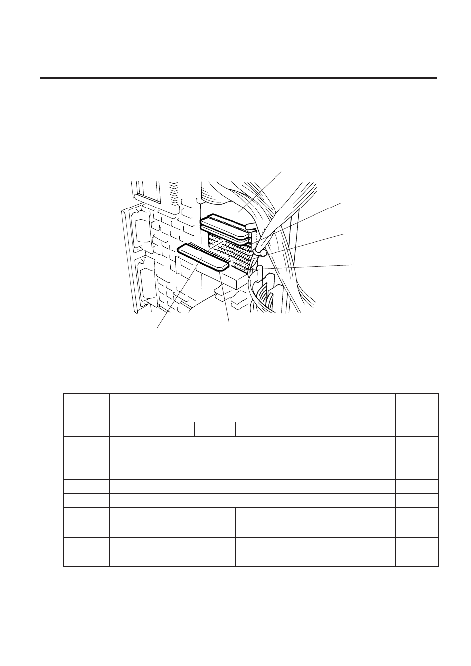
1. Remove the top cover and left side cover. (See Fig. 2-1.)
2. Hold the memory module so that the Pin 1 is on the upper right, then attach the memory module
to the IC socket. Expanding the memory must be performed in sequence, IC19, IC20, IC21,
IC22, IC23 and IC24.
Fig. 3-9
(Revision Date: Feb. 10, 2000)
3.3 MEMORY MODULE
3. Reassemble the left side cover in the reverse order of removal.
■
Expansion memory and drawing size
*: The size for the tag paper is 138.0x997.0.
RAM
Capacity
1MB
1.5MB
2MB
2.5MB
3MB
3.5MB
4MB
IC No.
IC17, 18
IC17~19
IC17~20
IC17~21
IC17~22
IC17~23
IC17~24
Remarks
Standard
Option
Option
Option
Option
Option
Option
Max. drawing size (normal)
(W)x(H) (mm)
138.0 x 298.6
138.0 x 469.3
138.0 x 640.0
138.0 x 810.7
138.0 x 981.4
Batch
Strip
Auto-cut
*138.0 x 995.0
*138.0 x
991.0
*138.0 x 995.0
*138.0 x
991.0
Batch
Strip
Auto-cut
Memory Module
Pin 1
IC24
IC Socket
IC19
CPU PC Board