Toshiba B-570 SERIES User Manual
Page 101
6-11
EM18-33010A
6. DIAG. TEST OPERATION
DIP SW
DIP Switch 1
0: OFF (OPEN)
1: ON (SHORT)
DIP Switch 2
0: OFF (OPEN)
1: ON (SHORT)
Pin No.
0 0 0 0 0 0 0 0
8 7 6 5 4 3 2 1
1 0 0 0 1 0 1 0
8 7 6 5 4 3 2 1
Status
EXP. I/O
Expansion I/O PC board
Loopback test
OK: The circuit has no problem.
NG: The circuit has a problem or loopback jig
is not attached.
OK
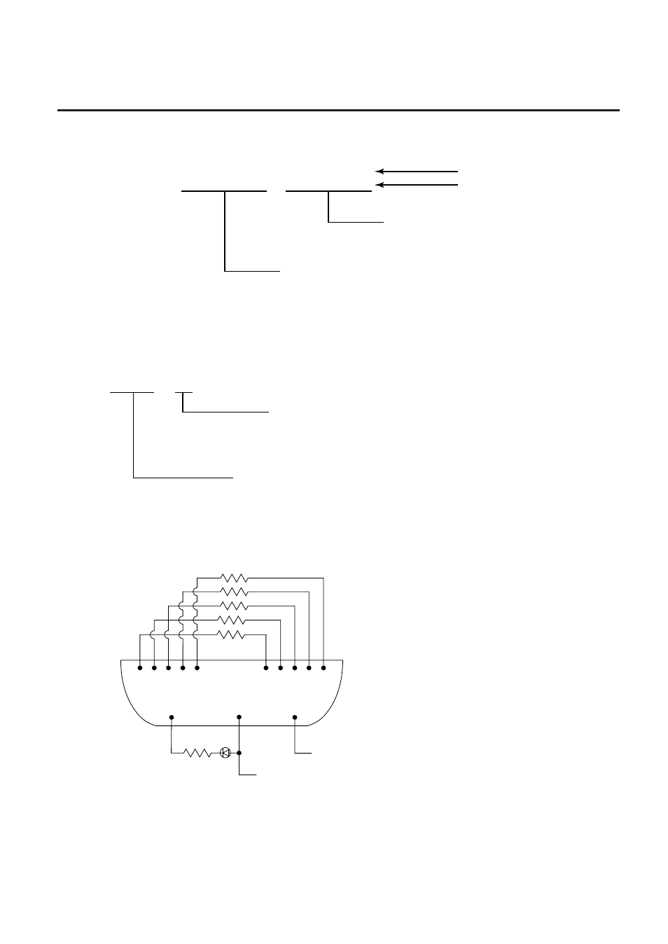
Connector: FCN-781P024-G/P
Fig. 6-3
For the loopback test, connect jig as shown below and check HIGH output / HIGH input and
LOW output / LOW input.
(Revision Date Jan. 13, ’95)
6.2 SELF TEST MODE
8
DIP SW Check
NOTE: The DIP switch 1-7 is to be set to 0 (OFF:OPEN) regardless of setting item.
9
EXP. I/O Check
1
2
3
4
5
7
8
9 10 11
300
Ω
x 5
12
15
300
Ω
Vcc
GND
21
See also other documents in the category Toshiba Printers:
- e-STUDIO222cp (16 pages)
- e-STUDIO382p (22 pages)
- Copier (78 pages)
- e-Studio Imaging 5520c (288 pages)
- multifunctional digital color systems e-STUDIO4540C (282 pages)
- B-852 Advance (2 pages)
- GA-1121 (118 pages)
- 720T (8 pages)
- 305 (168 pages)
- TEC EO1-32004 (94 pages)
- TEC DRJST-51 (19 pages)
- MULTIFUNCTIONAL DIGITAL COLOR SYSTEMS 2830C (178 pages)
- B-SP2D (50 pages)
- R-TH10 (86 pages)
- B-682-QP (157 pages)
- B-680-QQ (32 pages)
- e-STUDIO 281C (8 pages)
- TEC EO1-33027E (122 pages)
- MULTIFUNCTIONAL DIGITAL COLOR SYSTEMS e-STUDIO5520C (210 pages)
- 7FM03281000 (34 pages)
- B-570 (90 pages)
- GD-1270 (120 pages)
- ESTUDIO 230L (382 pages)
- 520 (7 pages)
- TEC EM1-33043D (46 pages)
- B-EP2DL (28 pages)
- TRST-A15 SERIES (31 pages)
- TEC B 452 (184 pages)
- TEC EO1-33016E (34 pages)
- B-670-QQ (34 pages)
- REMOTE RECEIPT PRINTER TRST-A00 (35 pages)
- e-STUDIO Printer/Fax/Scanner/Copier (4 pages)
- 282 (48 pages)
- B-480-QP (170 pages)
- B-450-QQ (28 pages)
- B-480-QQ (30 pages)
- B-SA4TP SERIES (114 pages)
- TEC EO1-13016 (24 pages)
- B-450-HS-QQ (34 pages)
- E.STUDIO 603 (216 pages)
- e-STUDIO 170F (244 pages)
- B-SA4 (2 pages)
- TEC EM1-33039E (34 pages)
- B-852 (2 pages)